


Patents Completed.
Page 20
If you've noticed an error in this article please click here to report it so we can fix it.
DRIVING AXLES. —Ridley. —No. 28,352, dated 24th December, 1907.—According to this invention, the rear axle (A) consists of a single shaft extending from one wheel to the other and having keyed on to it a central bevel wheel (ll) gearing with another bevel wheel (191) on the propeller shaft (C). The bevel gearing is enclosed within a casing (D) having an extension (D1) through which a differential shaft (E) passes. The differential shaft is connected by gearing to the hubs (Al-) of the driving wheels and the driving axle (A) so as to. allow either wheel La turn independently of the other. The hubs of the wheels are loosely mounted on the driving axle (A) which has keyed on to it at each end a driving pinion (F) meshing with two pinions ((I) loosely fitted on spindles carried by the hubs. These pinions mesh on their outer sides with internal teeth on gear rings (111), one at each
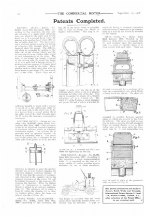
end of the shaft. These rings are of sufficient breadth to mesh with a pinion )1) keyed on to the differential shaft (E) in one case, and, in the other case, to derive motion from a second pinion (I) at the other end of the shaft through gears I2) to give the necessary compensating movement IGNITION DEVICE.—Delage and Another.—No. 10,855/07, dated (under Convention) 26th June, 1906. This invention relates to an improved method of igniting an explosive mixture within an internalcombustion engine. The cylinder (B) is provided with an ignition chamber (Al which is concentric with it. The piston rod of the piston (G) is extended at the other side of the piston as at II, and this
extension is adapted to enter the ignition chamber (A) an as to further compress the explosive mixture contained therein. It will be seen that the amount of compression obtained in the chamber (A) by the upward movement of the piston (G) will be further increased on the extension (11) entering the chamber. When the highest point of compression is reached, the charge is ignited by an ordinary sparkingplug (E). The extension (H) is made a loose fit within the chamber (A) so that, on ignition taking place, the flame can extend into the cylinder (B).
SPARE WHEEL ATTACHMENT.— Kemp.—No. 10,482, dated 14th May, MS.—According to this invention, the
rim (A) with a slightly of the spare wheel is provided riug. or flange (al) which is bell-mouthed. This ring is ar
ranged to slide over the rim (6) of the ordinary wheel, whilst a clip (c) is adapted to engage the other side of the rim. This clip is connected by means of a flexible connection )(3) to a T-piece (c4). The shank (e2) of the T-piece is screw-threaded and passes through a hole in a bracket (E)
on the rim (Al. A butterfly nut (D) is provided for tightening up the clip.
FIRE ENGINE.—Brindle.—No. 28,066, dated 20th December, 1907.—According to this invention, a quick steam-generating boiler (1). is mounted on the rear of a motor vehicle 21, which provides accommodation for two or three attendants.
The boiler is provided with the usual unions (5) to which the flexible steam conductors may be attached. A pipe or nozzle (4) having a universal connection with the boiler is arranged to be manipulated by a wire (6) and winch (7) mounted on the vehicle.
TIRES.—Sadler.—No. 16,721, dated 22nd January, 1908.—Mounted on the felloe (a) of the wheel is a pneumatic tube (6)„ and mounted upon this pneumatic tube is a series of metallic shoes (c) in close contact with each other. These are
divided transversely by A partition (1.1) to form two compartments into which blocks of hard wood are placed. The shoes are mounted in position between annular plates (e) which are secured to the felloe by bolts V). The shoes are held in position by bolts (g) passing through elongated holes (/n) formed therein so as to allow radial play of the shoes upon the pneumatic tube (b). A solid indiarubber ring
may be used in place of the pneumatic tube, as shown in Fig. 3.