


Recent Developments in Machine Tools.
Page 2
Page 3
Page 4
If you've noticed an error in this article please click here to report it so we can fix it.
Alfred Herbert, Ltd., of Coventry and London, introduce New Models to Meet the Latest Requirements of Motor Manufacturers.
The remarkable development of the motor industry has had a very farreaching effect, and its influence has been keenly feit in most other branches uf the engineering business, and, possibly, the rapid development of highspeed machine tools is due more to the progress in the automobile industry than to any cause arising from other brandies of the engineering trade. Amongst manufacturers of machine tools the name of Alfred Herbert, Ltd., has long been recognised as that of a manufacturer whose well-designed machine tools are capable of producing intricate detailed parts with a high degree of accuracy, at low cost tor labour, and with a very high speed of production. A few of this company's latest machines will be described in tnis article.
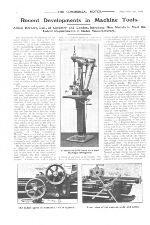
The simplest, and, possibly, the most novel of that company's latest introductions is the ball-bearing sensitive drill, which we illustrate herewith. ln this tool every spindle and every rotating part has been mounted on single-track ball bearings, and the results of the adoption of this type of bearing are a very high speed combined with high efficiency. The fact that the drilling spindle itself is mounted on ball hearings and has no sleeve bearing whatever permitsof its being run at the highest speeds without any heating, and without wear. At the same time, the saving in friction all over the machine allows of the feed of the drill being quicker, and much larger holes may be drilled than are possible on the usual types. of sensitive drills. A repre sentative of " COMMERCIAL MOTOR," on a recent visit to the works at Coventry, had opportunities for witnessingthe performances of all the company's new models, and the work done by this drill was truly remarkable.
On the single-spindle machine which we illustrate, a i-inch-diameter hole was drilled to a depth of one inch in a slab of cast iron in the short space of four seconds, the drill running at a speed of about 600 revolutions it minute. A further test with it A-inch drill, at a spindle speed of 2,051) revo1 itions a minute, the dril: p:memited to
speeds would absolutely be impossible on any ordinary type of sensitive drill.
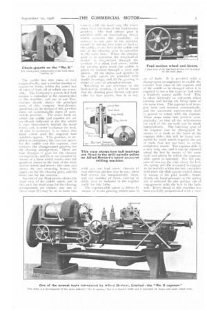
The arrangement of the drill feed is by means of a steel rack and pinion, and a double-ended hand lever which is held in a spring socket so that it can be pulled out either way to the length necessary for the work that is being done. This type of machine is provided with a countershaft on which are fast and loose pulleys (A), and mounted on the same spindle is a two, peed pulley from which an endless belt transmits the drive to the two-speed pulley that is mounted at the top of the drilling spindle. This latter pulley, by the way, is mounted as shown in the small sketch on the next page, and it will be seen that the pull of the belt does not transmit any bending effort to the drilling spindle. The endless belt is guided by two broad jockey pulleys which are mounted on an arm that projects from the back of the column. Roth these jockey pulleys are adjustable; one of them is adjustable along a diagonal line in order that the belt May be brought in line with either the upper or the lower step of the cone on the drilling spindle. This type of machine appears to be the last word in sensitive drills, and it is made with one, two. three or four spindles. Another new tool recently introduced is the " No. o Capstan,'' several views of which we reproduce. This particular machine is a de vel opm n t of the Company 's " No. ö Capstan lathe," but it has been built to take a wider range of work, and it is, Of course, of greater strength and power. It is particularly suitable for machining articles that are made from steel blanks, as, in addition to the coarse feeds which are needed for machining castings, it ha& feeds fine enough to do accurate work with high-grade steel. The head-stock has a hollow spindle of high-carbon steel and will admit bars up to 3; inches in
diameter; the nose of the spindle is flanged so that chucks can be attached to it without an intermediate face plate, thus the overhang of the chuck is kept down to a minimum amount. The saddle has nine rates of feed longitudinally, and a similar number oi transverse feeds, whilst the turret. has 18 rates of feed, all of which are reversible. The Company's patent dial feed inotion is embodied in the construct ion of this machine, and one of our illustrations clearly shows the principal parts “i this compact, feed-changespeed box; in the design of this gearbox there are unmistakable signs of auto mobile practice. The exact feeds on which the saddle and capstan are set are clearly indicated on the dial which is seen immediately behind the hand wheel, aed, in order to change the feed, all that is necessary is to rotate this hand wheel until the required feed I umbers appear. This gearbox, in addition to contitiniry-, the traverse speeds for the saddle and the capstan, also contains the change-speed gearing for the chasing arrangement. There are four changes of gear for the chasing arrangement, and these are actuated by means of a lever which works over the yin-air:int shown in the view of the feedmotion wheel and levers: this view also shows the two reversing levers; the upper one for the chasing gear, and the lower one for the traverse.
Another of our illustrations shows the front .view of the saddle apron, and in this view the dead stops for the chasing arrangement are shown; any one of these stops (Cj may be set to come into
canttlet ysith the fixed stop (13) xyhiell abuts in ;-:n the front of the feed-motion
gearh:SN. he feed release gear is proyitlod with an interlocking device which prevents the possibility of damage to any part oi the machine caused he haying two rates of feed of the saddle, at one feed of the saddle and one ot the chasing gear in operation at the sante time. When the chasing gear is in oneration the longitudinal illation is trat.:ilnitted through the edium of a short lead screw, whilst for turiting plain work the saddle is given its motion through a rack and pinion. All the shafts and spindles in the saddle apron an provided with double hearings, and all the gearing is either of sJ:et1 or phosphor-bronze.
Reverting to our reference to the ftlCd-1-11nti)11 gearbox, it will be found That the chasing gear therein only provides fItt four speeds, that, is to say, with airy one lead screw, threads of four di :Totem pitches may be cut ; these lead screws are comparatively short, tint] any number of them, varying in pitch, TI1:11be included in the regular outfit for this lathe.
The capstan-slide apron is driven by means of worrn gearing which runs in an oil bath. It is provided ‘vith change-gear arrangement to enable die relative feed rates of the capstan and of the saddle to be changed when it is required to use a fine capstan feed with a relatively coarse saddle feed. This is often necessary or advisable when turning and boring are being done at the same time. The capstan is of hexagon form and revolves automatically, and the automatic capstan-stop shaft is geared to rotate with the capstan. .these stops come into position automaticaliv, so that all the adjustments for each of the six tools can be made independently. The indexing gear of the capstan can be disengaged by means of a knob at the front of the capstan slide ; this will be found very useful for work which requires the use of tools that are too long to swingcompletely round. The capstan slide is a very long one, and it can be adjusted along the bed by means of the same rack and pinion by which the capstanslide apron is operated. For the purpose of moving the slide along the had, the spring pin (D) is caused to engage in the hole (E) within the bed, and while held there the slide can be racked along by means of the pilot handle ; immediately the hand pressure on the spring pin is released the pin springs out of engagement with the hole in the lathe lied. Every detail of this machine has been carefully proportioned with a view
to its standing up to the heavy work which it will be called upon to perform in any modern machine shop.
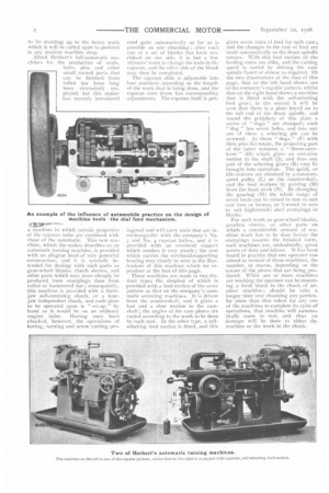
Alfred Herbert's full-automatic machines fr,r t he production of studs, bolts, pins and other small turned parts that can be finished from rolled bar have long been extensively employed, but this maker has recently introduced
roar
a machine in which certain properties of the capstan lathe are combined with those of the automatic. This new machine, which the maker describes as an automatic turning machine, is provided with an all-gear head of very powerful construction, and it is specially intended for dealing with such parts as gear-wheel blanks, clutch sleeves, and other parts which inay more cheaply he produced from stampings than from rolled or hammered bar; consequently, this machine is provided with a threejaw self-centreing chuck, or a fourjaw independent chuck, and each piece to be operated upon is " set-up " by hand as it would be on an ordinary engine lathe. Having once been chucked, however, the operations of boring, turning and screw cutting pro. ceed quite automatically so far as is possible on one chucking; after each one of a set of blanks has been machined on one side, it is but a few minutes' work to change the tools in the capstan, and the other side of the blank may then be completed.
The capstan slide is adjustable into four positions according to the length of the work that is being done, and the capstan cam drum has corresponding adjustments. The capstan itself is pen tagonal and will earn tools that are interchangeable with the company's No.
and No. 4 captan lathes, and it is provided with an overhead support which renders it very steady ; the arm which carries the overhead-supporting bearing may clearly be seen in the illustrations of this machine which we reproduce at the foot of this page.
These machines are made in two distinct types the simplest of which is provided with a feed motion of the same pattern as that on the company's automatic screwing machines. It is driven from the countershaft, and it gives a fast and a slow motion to the camshaft ; the angles of the cam plates are varied according to the work to be done by each tool. In the other type, a selfselecting feed motion is fitted, and this gives seven rates of feed for each cam; and the changes in the rate of feed are made automatically as the drum spindle rotates. With this feed motion all the feeding cams are alike, and the cutting speed is varied by driving the cam spindle faster or slower as required. Of the two illustrations at the foot of this page, that on the left hand shows one of the company's regular pattern, whilst that on the right hand shows a machine that is fitted with the self-selecting Iced gear ; in the second it will be seen that there is a plate keyed on to the tail end of the drum spindle, and round the periphery of this plate a series of " dogs " are clamped; each " dog " has seven holes, and into any one of these a selecting pin can be screwed. As these " dogs " (F) with their pins (G) rotate, the projectingpart of the latter actuates a " throw-overlever " (H) which gives an end-wise motion to the shaft (J), and thus any pair of the selecting gears (K) may be brought into operation. The quick, or idle motions are obtained by a constantspeed pulley (L) on the countershaft, and the feed motions by gearing (M) from the head stock (N). By changing the gearing (1) the whole range of seven feeds can be raised in rate to suit cast iron or bronze, or lewered in rate to suit high-tensila steel stampings or blanks.
For such work as gear-wheel blanks, gearbox sleeves, or other parts on which a considerable amount of machine work has to be done before the stampings assume the finished form, such machines are, undoubtedly, great savers of time and labour. It has been found in practice that one operator can attend to several of these machines, the number, of course, depending on the nature of the pieces that are being produced. While one or more machines are working the operator can be mounting a fresh blank in the chuck of another machine ; should he take a longer time over chucking any particular piece than that taken for any one of the machines to complete its cycle of operations, that machine will automatically come to rest, and thus ro damage will be done to either the machine or the work in the chuck.