


A Spring-balanced Tailboard
Page 52
If you've noticed an error in this article please click here to report it so we can fix it.
"ANimproved tailboard or loading ramp is described in patent No. 677,735, by J. S. Robson, Ltd., Durham .Road Coachworks, Blackhill, Consett, Durham. The aim is to maintain closure and in some measure to balance 'the weight of the board. • The scheme is shown in perspective in the draWing... The board is hinged in the usual way at points 1 on the rear body member. Channel-shaped, guides (2) receive the sliding ends of levers 3 pivoted at lower points 4. The levers are heavily loaded in the closing dine t on by pairs Of springs (5) attached to the side members of the body. When the tailboard is pulled down, the levers slide in the guide channels at the same time tensioning the springs, thus partly, balancing the weight. The
view n chain lines illustrates the position of the parts when the tailboard is horizontal.
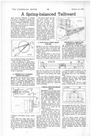
• A TORSIONALLY FLEXIBLE PROPELLER SHAFT
PATENT No:674,293 (Fiat Societa 1 per 'Azioni, Turin, Italy) gives details of a propeller shaft capable a measure of fl giving a mexibility in a rotary sense. The basis of the patent is the means for preventing unwanted vibrations, particularly during critical speeds. The shaft has large ends and a reduced portion over most of its length, as shown at I. Surrounding the shaft, a and revolving with it, is tube (2); this is supported at one end by a roller bearing (3) carried by the chassis; and at the other end by a rubber sleeve.
A42
The driving spider (4) and the driven spider (5) are
splined to the shaft. The outer tube, although revolving with the shaft, is not coupled thereto, and does not therefore affect its torsional
resilience. But at its midpoint, and possibly at others, rubber bushes (6) under some pre-compression, form a firm location for the shaft for preventing vibration. It is proposed to position the resilient pads by forming grooves in the surrounding tube.
A PNEUMATIC-TYBED ROAD ROLLER
SAID to be more effective than the usual rigid type, a pneumatic-tyred road roller is shown in patent No. 677,205. The patentee is Etablissements Richier, Paris. The drawing shows a view of the front axle which is fitted with fourwheels complete with pneumatic tyres. Each pair of wheels rocks on beam 1 and the two beams Can rock further about the central pivot (2) so that all wheels 'bear on the ground with equal force. The rear axle is similarly fitted up, but has five wheels located in staggered relationship with the front ones. This
enables complete n
coverage to be given to the piece of road over which the roller is working.
A METAL-SPRAYED BRAKE DRUM
DATENT No. 677,144, comes 1 from the Ford Motor. Co., Ltd., 88, Regent Street, London, W.1, and deals with a method of facing a light-alloy brake drum with a hard-wearing surface_ Cast-iron liners have, in the past, been used for this purpose, but their heatdissipating properties are poor, and the thief aim of the present scheme is to speed up the 'disposal of heat. An aluminium-alloy drum is internally coated with two metals by the spraying process. A gas torch (1) provides some pre-heat while the inner surface is sprayed by the two guns (2 and 3). The preferred metals are zinc and stainless steel of the 18/8 type, in the proportions of 30 per cent. zinc to 70 per cent. steel. The zinc imparts a high heat-conductivity to the mixture, Whilst the stainless steel gives a good wearing surface.
MECHANICAL SERVO FOR HYDRAULIC BRAKES
A HYDRAULIC braking system in 1-"k which the driver's effort is amplified by a mechanical servo device driven by the transmission, is shown in patent No. 667,653 (the Automotive Products Co., Ltd., Tachbrook Road, Leamington Spa). The servo device consists of a behind-the-gearbox friction brake, the reaction from which is used to operate the master cylinder.
A general layout shown in the drawing, in which is the gearbox, 2 the friction. propellershaft.
The friction unit is a brake-like assembly, and is, itself, operated by hydraulic pressure from the pedal, transmitted via pipe 4.
In operation, the driver's pedal moves a small piston (5) to the right and energizes the servo unit. The running friction in the unit endeavours to turn the back-plate, and in doing so pulls a rod (6). The pull is transmitted via a bell-crank to the master piston (7) which moves to the right and provides full braking pressure in the pipe-line
(8) As es
the master • piston moves, it relieves the pressure on the smaller piston owing to the telescopic construction, and so creates a state of balance for any position of the pedal. Should the servo-system fail, the small piston would eventually operate the main piston.