


Air Springs are Adjussable and Self-damping
Page 30
If you've noticed an error in this article please click here to report it so we can fix it.
Pressure can be Varied at Will to Suit the Conditions of the Moment. Energy is Automatically Converted to Heat
AETALLIC springs, as commonly used on road vehicles, Mare not adjustable to the load they have to support and, consequently, they cannot be an ideal design for the suspension of the vehicle in all states of loading. They are probably unsuitable for conditions of no load and barely adequate for those of over load.
A kind of adjustable spring which approaches nearer. to perfection is that represented by the Usual pneumatic tyre, namely, compressed • air enclosed in a chamber of slightly varying volume. Air as a springing medium affords the special advantage that 'much of the energy exerted in a shock is convened to heat,, whereby the pressure of the medium-.—assuming relatively good heat .conductivity—is not changed.
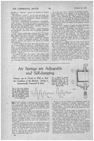
. Diagrams relating to the action of metallic springs show clearly that the amplitude 'of the Second rebound of a wheel is always larger than that of the first, for besides the falling weight, the releasing spring inereages the intensity. This
is shown in Fig. 1 (a). In the case of an air spring, however, only the first rebound shows the largest amplitude, the following rebounds being damped in both direction, as indicated in Fig. 1 (b).
Pressure in the air chamber of a piaeunsatie spring can be adjusted according to existing requirements. For instance, an unladen lorry can be run. wip only half the 'usual pressure. ,The Gruss air spring is a well-known example. and has proved the efficacy and satisfactory fuuCtioning of the scheme. Another device—of foreign origin—is the Rohrbach. In this, independent wheel suspension is 'employed, each air cylinder being coupled to a swinging arm, on which the wheel is mounted. Fig. 2 shows this device in section. It will be observed that a, rubber air bag is enclosed in a steel cylinder, shaped internally in such a way that no folds are caused and sliding movements are avoided.
The relatively thin-walled and shallow rubber container remains undeformed when .the system is in a position of maximum load. As the load is released, the bag expands, owing to its internal pressure. This, however, takes place during only a limited range, after which the rubber separates from the metal walls. When the rebound occurs, the container iscompressed again, the rubber re-assuming its original Shape. To help,in avoiding folding of the rubber,
the cylinder is of large diameter, but short stroke.