


A NOVEL DIFFERENTIAL GEAR.
Page 34
If you've noticed an error in this article please click here to report it so we can fix it.
A Résumé. of Recently Published Patents.
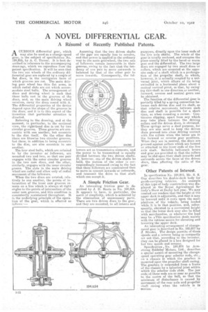
ACURIOUS differential gear, which may also be used as a change-speed gear, is the subject of specification No. 184,916, by A. C. Turner. It is best described in reference to the accompanying drawings, which we reproduce from the patent specification. It will be seen that the two sun wheels of the ordinary differential gear are replaced by a couple of 'flat discs, in the contiguous faces of which grooves are cut. The main driving gear wheel has thin flat arms, in which radial slots are cut which accommodate steel halls. The arrangement of discs and driving wheel is such that these balls rest in the grooves of the discs, and, as the •main driving wheel revolves, carry the discs round with it. The differential properties of the device depend upon the shape of the grooves in the discs, and it is to this aspect of the invention that partieular attention is directed.
Referring to the drawing, and at the moment, in particular, to the sectional view, the right-hand disc is cut by two circular grooves. These grooves are concentric with one another, but eccentric to the disc itself. On the other disc there are likewise two circular grooves, but these, in addition to being eccentric to the disc, are also eccentric to one another,
The four steel balls, whieli are referred to by the inventor as followers, are mounted two and two, so that one pair engages with the outer eiroular grooves in the two cam discs, and the other, similarly, engages with the inner -circular groove. The slots in the main driving wheel are radial and allow only of radial Movement of the followers.
When the two discs are rotated, relatively to one another, the points of intersection of the inner cam grooves remain on a line which is always at right angles to the points of intersection of the outer cam grooves, and this condition is consistently maintained throughout. It lathe underlying principle of the opera. ion 'of the gear, which is. effected as follows Assuming that the two driven shafts of the gear are equally free to revolve, and that power is applied in the ordinary way to the main gearwheel, the two sets of followers remain immovable in their grooves, owing to the fact that the tendency of one pair to move outwards is balanced by that of the other pair to move inwards. Consequently, the fol lowers act as transmissive elements, and the power to he transmitted is equally divided between the two driven shafts. If, however, one of the driven shafts be held, the motion of the other is correspondingly increased owing to the fact that these followers are constrained then to move in concert inwardsor outwards, and transmit the drive to that shaft which can accept it.
A Simple Friction Gear.
An interesting friction gear is described by J. D. Roots in No. 184,854. It appears to have, in particular, the merit of simplicity, which is achieved by the elimination of unnecessary parts. There are two driven discs to the gear, and they are mounted, to all intents and purposes, directly upon the inner -ends of the live axle shafts. The whole of the gear is totally enclosed, and occupies the -place usually filled by the bevel or worm gear and the differential. The two large discs are engaged by two small discs or rollers, which are-nieunted at the opposite ends of a shaft which is a prolongation of the propeller shaft, to which, however, it is actually coupled by a universal joint, which allqws of its being swivelled in a horizontal plane about a central vertical pivot, so that, by swinging this shaft in one direction or another, forward, reverse and neutral gears can be obtained. • The function of the differential gear is partially filled by a spring connection between each driven disc and its shaft, so that relative. movements between each disc and shaft is. possible for a short time, as when rounding a corner. Continuous slipping, apart from any which may take Place between the driving rollers and the driven discs, is obviated. These springs serve a dual purpose, for they are also used to keep the driven discs pressed into close driving contact with the rollers when the latter are in the forward or reverse gear positions. When they are in neutral, the, discs are pressed against collars which are formed or attached to the inner ends.of the live axle shaft. Suitable bell-crank levers and gear are provided so that the rollers may he slid upon their shalt inwards and outwards across the facesof the driven discs, thus affecting the ratio of the gear.
Other Patents of Interest.
In specification No. 184,915, Mr. S. S. Guy describes his double-deck body for goods-carrying vehicles. An example of this type of body construction was displayed at the-Royal Agricultural Society's Show at Derby last year. We may remind our readers that the height of the upper deck is adjustable, and that it may be lowered until it rests upon the main platform of the vehicle, being loaded while it is in that position, and, subsequently, elevated to a convenient height so that the lower deck may also be filled with merchandise, or whatever the load may be. a This specification deals mainly with the various means for elevating and loseerirg the upper deck. An interesting arrangement of changespeed gear is described in No. 185,017 by 3. RhodeS. The design permits of three speeds and a reverse being so compactly set out that, according to the inventor, they can be placed in a box designed for but two speeds and reverse. Specificatiou „No. 184.'974 by Armstrong Siddeley Motors, Ltd., describes a special means of mounting the changespeed operating gear selector rods, etc., on •-a chassis in which the gearbox is mounted upon the propeller shaft casing. The gearbox is suspended from a frame of the chassis by a spherical joint withIn which the selector rods slide. The jaw. ends of these rods are as near as possible to the centre of the ball, so that. the minimum of disturbance is caused by movement of the rear axle and propeller shaft casing when the vehicle is in motion.