


PRODUCER PLANT FOR VEGETABLE FUELS.
Page 30
If you've noticed an error in this article please click here to report it so we can fix it.
A Resuin6 of Recently Published Patent Specifications.
LT.-COL. DAVID J. SMITH, whose name is already identified with producer plants, describes in his specification, No. 240,22(1, certain improvements in such apparatus which are claimed to render it particularly suitable for the use with vegetable fuels such as char
coal, etc. Although no mention is made of the application of the improvement to motor vehicles, the subject is of special interest, particularly after the successes achieved at the recent FrancoBelgian trials.
In this producer two separate chambers are provided for combustion, consisting of an inner circular chamber and an outer chamber surrounding the other in the form of a ring. Each of these is provided with a grate and ash-pan. There is no communication between these ash-pans excepting through the Ares which are in the two chambers.
Briefly, the action is as follows:— The combustion is slow in the outer chamber, which serves to remove any moisture from the fuel and raises the gases to such a temperature that they can be dealt with by the inner fire. In the present invention the concentric combustion chambers are intended to enable fuel to be used having a large volatile or moisture content, the outer fire functioning to raise the temperature of the fuel so that it can be dealt with by the inner fire by the addition of further air. One of the features of the invention is that in the outer fire the air rises in its path through the fuel, and then passes in a downward direction through the inner chamber. A hopper is provided in which the fuel is slightly warmed, being situated above the fires, and from which it is fed to the fires. Steam may be generated by means of jackets round the gascollecting box or round the gas pipe, and added to the air passing into the outer combustion chamber.
Improvements in Pressure-fed Petrol Tanks.
MESSRS. PANHARD AND LEVASSOR show an improvement in pressure petrol tanks in their specification
NO228,524. The object of this invention is to enable the filler cap of a pressure tank to be removed to permit the tank to be refilled, or the ear to stand for a long time without the pressure in the tank decreasing to such an extent that the engine cannot be started without pressure being pumped In) by means of a hand pump.
The illustration shows diagrammaticc46
ally the principle of the apparatus. The pipe through which the petrol leaves the tank for the carburetter is provided with a valve at its lower end. An air chamber is provided which maintains the pressure on a portion of the petrol, so that sufficient fuel is always under pressure to enable the engine to be started, no matter how low the pressure may be in the main tank. Other applications are shown in which the air chamber is formed by partitioning off the main tank.
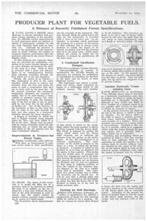
A Crankshaft Oscillation Damper.
THE lEsterreichische Daimler Motoren
Aktiengesellschaft, of Austria, in specification No. 217,928, describe an apparatus for damping the oscillations of crankshafts by attaching the flywheel to the shaft only by means of some frictional device.
The right-hand view shows a crankshaft and driven shaft connected by means of a multi-plate clutch in the ordinary manner. The outer member of this clutch is keyed to the crankshaft, whilst the inner member is shown as being integral with the driven shaft. The clutch is released by pulling the sleeve which slides over the driven shaft outward, and so releasing the pressure from the spring on the multiplates. So far, the arrangement is of ordinary construction. The outer member of the clutch is formed in the shape of a cone, on which the flywheel is mounted. A member is bolted to the flywheel so as to form an abutment for the spring to bear against. This spring does the double duty of pressing the clutch into engagement and at the same time forcing the flywheel on to its cone. The., amount of friction set up between the flywheel and its cone is regulated so that there is sufficient friction to drive the vehicle in the ordinary way, yet slipping in the case of a audclen extra load is permitted. The righthand view shows another way in which the invention can be carried out. It will he seen that a driving plate and its clutch are attached to the crankshaft as usual, but that thd heavy rim of the flywheel is forced on to its cone by spring pressure only.
Packing for Bail Bearings.
JOHAN Erik Eriksson, of Sweden, de scribes in specification No. 224,915 a construction of flange for ball hearings which he refers to as a packing. By this we surmose he means these flanges ro be oil retainers. The invention appears to be for a type of flange which cannot be slid over the shaft from the and, owiim to some enlargement, such .as a flange or web of a crank. In such cases it-is necessary to split the flanges in halves, which often results in oil leakage at the split. In the present ease the flanges are double, one being placed over the other as shown. They are both split, but the splits are staggered so as to prevent leakage.
Another Hydraulic Transmission Gear.
LOUIS RENAULT, in specification
No. 237,210, shows what is described as a hydraulic transmission gear, but, in reality, we think it might be better described as a hydraulic clutch, as, although it may enable one shaft to drive another at a reduced speed, it is not possible with devices of this kind to obtain an increase of torque. In the present invention the shaft on the left is the driver, to which is keyed an impeller. To the driven shaft on the right is keyed a member provided with vanes, somewhat resembling the outer member of a turbine. These two members are enclosed by a casing which is non-revolving. Attached to this casing is a cylinder, which is in communication with the casing through the passage shown, and is provided with a piston which can be controlled.
• Clutching and declutching effects are produced as follow :—For free running there is just sufficient fluid in the apparatus to enable the impeller on the driving shaft to revolve without causing reaction in the vanes of the member on the driven shaft so long as the piston is nearly withdrawn ; but, when the piston is pressed into its cylinder, it forces the fluid into the casing and sets up a reaction in the vaned member on the driven shaft and so transmits power. According to the amount the piaon is pressed home so will the speed of the driven shaft increase, but the torque will not increase with a low speed.