


Inboard Brakes
Page 60
If you've noticed an error in this article please click here to report it so we can fix it.
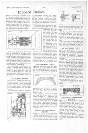
1".1-1E usual location for brakes is on the road wheels, but this means. that there is a definite limit to size and shape. A breakaway from conventional practice is shown in patent No. 770,117 (C. Paillard, 9 rue d'Astorg, Paris), the object being to place the brakes in a situation where they can be large in size and increased in number, and have the advantage of adequate cooling.
As shown in the drawing, the braking gear is contained in an axle casing although the scheme is applied only to • non-driven axles which usually have no casing. The brake is of multi-plate construction and is operated by the movement of hydraulic units (1). An alternative construction employs external contracting shoes, and a third scheme uses „ electro-magnetic engagement.
The whole unit is oil-immersed for cooling. Although the oil reduces the co-efficient of friction, the increased number of units offsets this. The oil may be splash-circulated or a pump can be incorporated. The axle-may also be provided with conventional brakes as shown at 2.
A GAS-TURBINE ENGINE
PATENT No. 770,408 discloses a gasturbine power unit for a road vehicle, comprising a piston engine used purely as a gas generator and a ttirbine for the actual power output. (Armstrong Siddeley Morors, Ltd., Park Side, Coventry.)
The basis of the patent is the use of a non-choking turbine, the patent defines choking as a condition in which• the gas velocity reaches the local velocity of sound. In Order to control this feature, the gas-generating engine is provided with means for varying its compression.
The drawing shows a section through • one cylinder of the engine. Ills a twostroke, pressure-charged by a geared-up compressor (1). The " air is fed to the working space through extra large ports (2) • in the cylinder •wall. The exhaust ports (not shown) are also large and extend higher up the cylinder than do the inlets.
Compression ratio is controlled by a piston-like plug (3) in the cylinder h e a d. This can be screwed up or down as required by a nut (4) which is externally formed into a wormwheel. The wormwheels of all the cylinders are moved in unison by a common worm shaft.
The patent gives full details of the timing diagrams and shows graphs illustrating the gas flow. It also gives a brief description of the turbine itself.
NON-CRACKING TYRES
HEAVY tyres quite often have their useful life curtailed by the forniation of cracks which admit water and dirt, and so cause damage long before
• the tread is worn away. A metholl of preventing this is shown in patent No. 769.258. (The B. F. Goodrich Company, 230 Park Avenue, New York, U.S.A.) The suggested remedy is to cover the tread with a thin layer of butyl rubber as shown at I. Naturally, it is soon worn off the working face, but it remains in the indentations and is said to have withstood tests of up to 20,000 miles without a crack appearing. Tyres not so treated, under similar conditions, showed up to 100 cracks in the tread, some of which extended completely round the lyre.
INSERTS IN LIGHT-ALLOY PISTONS
THE,ring grooves in an aluminiumalloy piston, particularly that at the top. are prone to wear caused by load and temperature. A scheme for castingin ring carriers, without trouble arising
from differential expansion, forms the subject of patent No. 769,528. (R. Daub, West Caldwell, Nest'Jersey, U.S.A.) The drawings show (left), a piston in the as-cast condition. The inserts (1) are made from hard metal and bent outwards to form a key in the alloy. They are in eight separate pieces and radiate outwards like the spokes of a wheel.
The right-hand drawing shows the piston after machining. The loop of the insert has been machined off and the groove cleaned out to receive the ring.
AN OIL-COOLED PISTON
AN oil-cooled piston shown in patent. No. 769,919 is intended principally for oil-engined road vehicles and is claimed to he effective in action and simple to dismantle. (May bach Motoknbau G.m.b.H., Friedrichshafen, Germany.)
in this design, the crown of the piston with its ring grooves is a separate detachable member and can be unbolted and removed from the piston at the top end of the cylinder. In the example shown, cooling oil is fed via the pipe I into an annular channel (2) which is very close to the rings. The oil divides into two streams which meet again at the other side and pass through a duct (3) intci a second channel (4). Here again the stream divides and reunites to traverse a third channel (5). . It finally makes its exit through a central recess and the discharge bore 6.
No details are given of the way in which the oil is supplied to the moving piston.
. A TREATMENT FOR BEARING SURFACES
TO reduce the friction of a bearing surface is the object of a.treatment described in patent No. 769,410. It is said to be equally suitable for steel or for the copper alloys such as bronze.
A paste of calcium Sulphate, dextrine and ammonium fluoride is applied to the work, which is then heated to 550° C. and held at this temperature for one hour.
The patent bears the names Minister of Supply. R. Samuel and Diffusion Alloys, Ltd., 18 Maddox Street, London, W.I.