


With Intent to Improve.
Page 22
If you've noticed an error in this article please click here to report it so we can fix it.
A Weekly Summary of Recent Patents, of Interest to the Maker and User a Commercial Motor Vehicles.
Most motor-vehicle users are well acquainted with that, type of carburetter in which a pilot jet is fed with fuel from a separate well or chamber, which well is in communication with the main float chamber and is also open to the grimsphere. The maximum amount of fuel available for this pilot jet is, as a rule, determined by the height of -the supply passage to the well. This passage usually takes the form of a vertical tube, the upper end of which opens into the fuel supply at a little distance below the main level of the fuel. The depth of fuel above the open end of the tubs in
the reservoir of fuel for starting purposes. The size of the orifice determulct the rate at which petrol flaws for replenishment of the supply. , • Julass Fagard, of 147, Corporation Street, Birmingham, in specification 105,309, describes a Modification and improvement of this type of fuel-feed device. His .invention comprises the combination of such an upstanding fuel sup-, ply tithe and the open chamber as we have described, this tube communicating at its lower end with the fuel passage from the float chamber; an auxiliary • pick-up jet from the choke tube communicating with the bottom of this open chamber below the discharge orifice of the supply tube; and the means whereby the supply of fuel to the said open chamber is automatically arrested when the suction increases and the main jet comes into actin. The auxiliary jet, therefore, is caused to cease to deliver fuel whedthe main jet is in full action ; the range of operations is a complete one, from pilot jet alone, through pilot jet -and. auxiliary jet to auxiliary jet and main jet until the final stage of main jet only is reached.
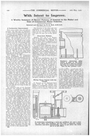
Wereproduce some of the drawings published with Fagard's specification, one being a sectional elevation of the carburetter, the other two beingsectional elevation and plan section, respectively, of the separate well and the various tubes therein accommodated. It will 113 seen that the arrangement of the pilot jet follows very closely previous constructions. The auxiliary jet is an annular one .surrounding the main jet. When the engine commences to run on a partially opened throttle, fuel is being drawn from the separate well by two2passages, one leading to the pilot jet, and shown in the small sectional elevation; the other leading to the annular auxiliary jet shown in main elevation.
The connection between the" atmosphere and this separate well is by means of the vertical wide bore tube which may be seen just to the right of the float chamber cap, it surrounds, at its lower end, the vertical tube which admits fuel to this separate well from the main supply. As the fuel level in the separate chamber is lowered until the bottom end of this atmospheric tube is open, air commences to rush down this tube and retards, finally completely arresting, the supply of fuel to the separate -well.
C62 The diameters of the tubes and other dimensions are so calculated that this rush of air is only sufficient totally to arrest the flow of fuel to the separate well when the main jet is fully operating.
Aluminium Pistons.
Humber, Ltd., and F. T. Burgess, both of Humber Works, Stoke, Coventry, in specification No. 105,312, describe a piston which is claimed to be an improvement upon a previous invention by the same patentees. It is particularly applicable where it is desired to make pistons for internalcombustion engines of soft material such as aluminium alloy. It has been found that such soft material wears more . rapidly at the lower bearing portions. It eliminates, also,• uneven wall-pressure which might be the result of unequal ex-• pansiotrof the metal of which the piston was made.
In the prior specification, one of the essentials of the piston described was that the lower edge should continue to exert. pressure upon the cylinder walls. In the case of a cast-iron piston this is generally obtained from the iiatural resilience of the metal. On pistons on certain kinds of material, such as the softer aluminium alloys, which is elastic, this might not occur, and accordingly the patentees suggest that the bellmouthed lower portion of the piston might be cut, as shown on the drawings, and an expanding ring be sprung inside go as continuously to press the skirt of the piston against the cylinder
Mixing Water Vapour with the Charge.
E. Sharman, of 51, Raymond Road, Upton Park, E., and another, have patented an arrangement whereby water vapour is drawn into the engine on each suction stroke in company with thecorn bustible mixture. A. small pipe, the inlet to which is baffled, draws Vapour from the top of the radiator just beneath the filler cap. • This pipe is led either to the inlet to the carburetter or to the induction pipe on the engine side of the carburetter, as may be desired. It is provided, at its lowest point; with a trap and ball valve which allows any water, which may inadvertently • be drawn into the pipe, to drain away. The inventors state that they have found thSt in practice using this apparatus, it is possible to dispense with a cooling fan and also that the usel of paraffin is considerably facilitated.