


AN EASY-TO-BUILD Fh
Page 26
Page 27
Page 28
If you've noticed an error in this article please click here to report it so we can fix it.
U.LIC ENGINE TESTER
EVERY operator who runs his own repair shop and overhauls his engines would, no doubt, like to be able
to erect an engine test bed. In normal times he is deterred by the expense involved in the purchase of the equipment and, to-day, by the difficulty of obtaining the equipment, even if he considered that the amount of work involved justified the outlay. .
These difficulties have been overconie, and the problem, to a certain extent, solved as the result of the ingenuity of Mr. W. P. Jones, of the Spares Recovery Department, T.T.3, Ministry of Supply. Repairers are recommended by the Ministry to construct such an engine load tester for their own use, whenever the work they a r e doing calls for such equipment.
T h e principal component is a used Fluid Flywheel. It is appreciated that such a unit is not so easily acquired but, given that,
the rest is easy, as HOUSING SUPPORT
t h e following description shows. The action of the Fluid Flywheel is, as will become apparent, the reverse of that which is customary in automobile prac tice. The flywheel . remains stationary and the rotor is used as the driving member, •
The equipment comprises three main components and some ancillary parts, as follow:—
(a) The test bed, which can be made up from old • • chassis side frames and cross-members, or of steel girders if they be available.
(b)The hydraulic unit, which is a used Fluid Flywheel complete with its universal couplings, primary and secondary shafts and the rear main-bearing journal of the crankshaft.
(c) the header tank, which can be a 10-gallon petrol tank equipped with a sight level gauge and suitable connections to the hydraulic unit.
(d) Ancillary parts: equipment ,necessary to the running of the engine under test and for the purpose of obtaining developed h.p. readings.
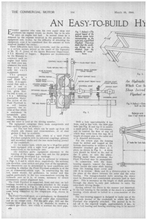
The layout of the test bed can be gathered by reference to Figs, 1, 2 and 3, which show, respectively, the sectional side elevation, cross section and plan view of the equipment.' The dimensions can be determined by local conditions and according to whether the Fluid Flywheel available is of the car or commercial-vehicle type. In constructing the test bed, joints should, for preference, be welded and this applies particularly to the two cross-members carrying the hydraulic unit as it is, of Course, necessary to ensure permanently correct alignment here.
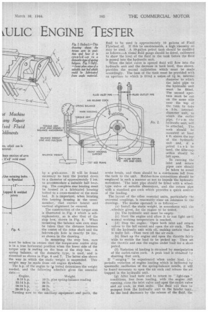
'The Fluid Flywheel is supported, front and rear, on ball bearings located in cross-members attached to the engine test bed, as shown in Fig. 1. It is free to rotate through an angle of approximately 20 degrees, the degree of movev ment being controlled by the torque-arm stop, shown in Fig. 2, The Fluid Flywheel must, as a preliminary, be dismantled for the attachment of inlet and outlet pipe connections and an air release cock. For the inlet pipe, drill out the 'existing filler plug hole to 11 in. diameter to receive a standard gas elbow, into which is screwed the inlet pipe.
CONTROL VALVE • FLUID RETURN PIPE FLUID FLYWHEEL HOUStNG DRIVING ROTOR ROTOR SHAFT SPIGOT RACE HOUSING SUPPORT CROSS MEMBER RETAINING COLLAR BEARING • TEST BED FRAME
Drill a hole approximately 3 ins. from, and in line with, the inlet pipe hole (see Fig. 2) and tap it to receive a. small petrol tap. For convenience, and to control the flow of any oil which may come from this tap, fit a length of copper pipe to the outer end of it, directed downwards.
For the return pipe the housing must be drilled and tapped at the bottom dead-centre to receive a 1-in. diameter standard gas elbow or T piece, as shown in Fig. I. A drain cock should be fitted at the end of the T piece, or into the elbow. Having made these provisions the Fluid Flywheel may be reassembled.
In connection with the fronthousing support, remove the sleeve which carries the rotor shaft bearing from the housing front cover and refit it in reverse. Make and fit a distance-piece to take the place of the sleeve between the rotor and the rotor bearing. The hexagon-headed bolts securing the sleeve must be discarded and countersunk setscrews used in their place. This is necessary as the length of shaft protruding through the sleeve 'is„ only just sufficient to carry the rotor-shaft driving flange.
Having refitted the sleeve in the manner just described, fit the ball bearing to the outside of the sleeve in a suitable housing, which should be bolted to a cross-member of the frame.
The rear-housing support is designed to make use of the rear main journal of the crankshaft to which the Fluid Flywheel was originally attached.. The journal is. to be cut oft to the required length, approximately S. ins., to take a ball bearing and bearing retaining ring to be secured I N. -74
by a grub-screw. It will be found r Use existing bolts in flywheel necessary to turn the journal down to a diameter of approximately 2 ins. to accommodate a suitable ball bear
5' -in lug. The complete rear bearing must be housed in a fabricated housing Lapped Er, welded bolted to a cross-member of the main
joints bed. It is important, when locating this bearing housing in the crossmember, that correct lateral and vertical alignment be ensured.
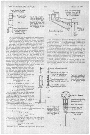
The construction of the torque arm is illustrated in Fig, 4 which is selfexplanatory, as is also that of the stop box, shown in Fig. 5. When mounting the balance arm care must be taken that the distance between
Fig. 4. the centre of the rotor shaft and the fulcrum-pin hole is exactly 24 ins., as shown in the drawing.
In mounting the stop box, care must be taken to ensure that the torque-arm centre strip is in a true horizontal position when the lower side of the torque arm is resting on the base of the stop box. A spring balance, of the domestic type, is used, and is mounted as shown in Figs. 6 and 7. The latter also shows the way in which the static weight is suspended. This weight may be made from old engine flywheels.
The h.p. of the engine to tip tested determines the weight needed, and the following schedule gives the essential data:—
Engine. Weight.
8-10 h.p. 10 lb. plus spring-balance reading
12-14 h.p. 20 lb.
18-24 h.p, ... 30 lb.
24-30 h.p. ... 50 lb. „ Turning now to the ancillary equipment and parts, the fluid to be used is approximately 10 gallons of Fluid Flywheel oil. If this be unobtainable, a high viscosity oil may be used .A 10-gallon petrol tank should be modified as follows:.—A visual fluid gauge should be fitted, calibrated to show the level of the fluid in the tank before the fluid is•passed into the hydraulic unit.
When the inlet valve is opened fluid will flow into the hydraulic unit and the decrease in tank level, thus shown, • provides the second calibration which must be made accordingly. The base of the tank must be provided with an aperture to which is fitted a union of lj in. interrial diameter to which the inlet pipe to the hydraulic unit must be fitted. The second aperture must be cut on the same side near the top of the tank to take a 1-in, internaldiameter unit, to which the outlet pipe, fr om the
FLUID OUTLET PIPE
F. 2. hydraulic unit, will be attached. The tank should be mounted at least 4 ft. above the top of the hydraulic unit and, if a petrol tank be used, the filler-cap orifice should be left open.
In running the inlet and return pipes care should he taken to avoid acute bends, and there should be a continuous fall from the tank to the unit. Rubber-hose connedtions should be employed in such a manner as not to impede the hydraulic movement, The inlet pipe should be fitted with a wheeltype valve of suitable dimensions, and the return pipe with a standard, gas cock which provides a quick control of the loading.
The layout of the other essential units, particularly the universal couplings, is reasonably clear on reference te the drawings. The modus operandi is as follows:—
(a) Install the static weight, in accordance witl the Schedule given, for the engine td be tested, (b) The hydraulic unit must be empty.
(c) Start the engine and allow it to run light until normal working temperature is reached.
4 (d) Stop the engine. Open both inlet and return valves to the full extent and open the air cock. Then fill the hydraulic unit with oil, making certain that it is really full. -Then turn off the air cock.
(e) Start up the engine and open the throttle fairly wide to enable the load to be picked up. Then set the throttle and run the engine under load for a short period.
(f) Variation of loading is obtained by manipulation of the outlet-valve cock. A peak load is obtained hy shutting that cock.
If " surging " be experienced when under load, i.e., periodic variation of engine loading which is indicated by spasmodic oscillation of the spring-balance needle, it will be found necessary to open the air cock and release the air trapped in the hydraulic unit, (g) After load tests and to return to " light-run " conditions, free from loading, with the engine ;Aill running, close the inlet valve and .open the outlet valve ind ,aie cock, in that order. The fluid will then be pumped. from the hydraulic unit to the header. tank.. As the load decreases by the release of the fluid, the engine revolutions will increase and the throttle should be adjusted accordingly. When. the fluid is completely exhausted from the hydraulic unit (check with visualgauge calibration on to header tank) close the outlet valve and air cock, The engine can now be tested for maximum r.p.m. and is completely free from load.
• A Ford 30 h,p. engine, running at 1,100 r.p.m., should lift and hold a static 'weight of 50 lb., plus 11 lb. reading on the spring-balance scale, equalling a total load of 61 lb, Whenever possible, brake-test curves should be obtained from the respective manufacturers, so that comparison may be made with results secured with the unit here.deseribed, It is recognized that heat will be generated in the hydraulic unit when under load conditions, but this is controlled, to some -extent, by the circulation of the fluid through the header tank. .Repeated tests on the experimental model have demonstrated that this heating condition does not affect the efficiency of the unit in relation to the purpose for which it is designed, i.e., to provide a convenient and cheap method of load testing a power unit. Maintenance requirements are negligible. Points requiring periodic lubrication are housing front and rear support bearings, link fulcrum pin, static-weight suspensionrod swivel, whilst flexible-hose connections should occasionally be checked, To those interested in the formula for x161 obtaining actual b.h.p. developed, the following information is given:— LVx 2rxN
As the length of the arm on this machine is fixed at 24 ins. (fromthe centre of the
casing) the expression, 2 r r, may be cal culated and used as a constant (C) in all
determinations of h.h.p. For a balance
arm of 24 ins., the constant is .00038 so that the formula may be written:— b.h.p. = Wx .00038 x .N.
The figure-33,000—representing ft.-lb. is also a constant, thurefore the final constant,
of this power unit will show that this .fignre -is almost exact.
• Some operators may look upon any form of engine tester purely as a luxury. This might apply were it a question of having to make an outlay of £200 or £300, but even then, if the amount of engine rebuilding is extensive, it would be money well expended.
To be in possession of such a piece Of equipment as here described is to have a means for checking up on engine performance on the bench and not on the road, An inefficient engine is very poor economy, but how is one to gauge an engine's output performance with any degree of accuracy without some form of testing device? The foregoing represents a straightforward solution and it has the merit of involving a moderaie outlay.
Further, the work involved in building is such as could be carried out, in the main, by semi-skilled labour, under direction from someone who had appreciation of the essential requirements.