


Know Your Air Brakes
Page 52
If you've noticed an error in this article please click here to report it so we can fix it.
Part 12 The Pressure Regulator
WITH more and more use being made of air pressure on the modern vehicle quite apart from braking, there have to be certain safeguards introduced into the system, to ensure that the use of auxiliary equipment does not deplete the supply to the brakes, or that build up is too slow to meet braking demands.
To quote one example—air assisted steering. Although the Westinghouse pressure steering does not waste air by exhausting to atmosphere, there is a minimum air requirement—and if other auxiliary items are in use as the engine is started, there can be some delay in obtaining a safe braking pressure throughout the vehicle. This feature is taken care of by the pressure regula
tor, which if arranged in the line before the auxiliary reservoir, will ensure that the main system is fully charged and remains so, the regulator not permitting the auxiliary system to drop the pressure in the main system below 60 p.s.i.
The valve also plays a part in systems using two reservoirs for braking and when fitted between the reservoirs will ensure that one is at a safe working pressure before the other is charged. A check valve is often fitted across the pressure regulator to allow air to return from the auxiliary reservoir to the brake reservoir if brake pressure is ever below the auxiliary pressure.
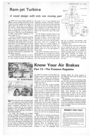
The pressure regulating valve is quite simple and not unlike the governor described earlier. Its base forms a chamber for an horizontal inlet port and dvertical outlet port and valve seat, the base also being arranged as a bracket for chassis mounting. The domed cover has four-stud fixing to the base—the cover carries the adjusting screw in the top with the coil spring and spring seating.
Between the two sections and secured by the four bolts is the diaphragm; secured through the diaphragm is a single valve that opens and closes the outlet port. Air pressure arriving at the inlet port will meet a resistance below the diaphragm that requires 60 p.s.i. to move. As this pressure increases so does the diaphragm move upwards against the spring pressure, in turn lifting the valve from its seating in the lower chamber.
Adjustment is made by slackening off the lock nut and turning the hexagonal-headed screw—clockwise will increase the pressure and vise-versa. Testing is also easy, as any leakage past the diaphragm will show at the small vent hole in the dome cover. This vent hole is situated just above the level of the bolt heads. Any alteration to the spring setting should be made with the aid of a pressure gauge inserted in the line, and by observing the pressure needed to open the valve.
The diaphragm will normally serve up to 12 months with safety, but should be replaced at that time regardless of whether in trouble or not. In terms of miles, this would be lathe region of 50.000.