


A Semi-locking Differential Gear
Page 52
If you've noticed an error in this article please click here to report it so we can fix it.
PATENT No. 692,528 shows a differential gear which functions normally under ordinary road conditions, but which will resist total slippage of one wheel on account of internal friction. The patentee is E. Wildhaber, 124 Summit Drive, Rochester, New York, U.S.A.
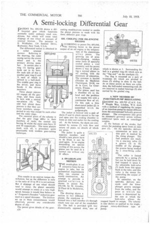
The differential action is obtained in a rather unusual manner. Referring to the drawing, the outer casing carries the crown wheel and is the primary driving mem ber. It carries also a ring (1) having gearteeth cut in its bore. On each side of this is another gear ring (2 and 3) each of which is splined to a half-shaft. The middle gear ring is the driver, and those beside it the driven members.
Three planet pinions (4) engage all the gear rings, and these mesh in turn with a central
sun-pinion • (5). The odd fact about these pinions is that they are loose members, unsupported in anyway except by each other and the outer rings: The essential point of the scheme is that the gear rings differ in their numbers of teeth, the central one having 36 whilst the outer ones have 33 and 39 respectively. The same planets mesh with all, a procedure quite practicable with modern gear-cutting
60i,&46
• technique.
This results in an uneven torque distribution, but as the difference is only in the ratio of 33 to 39 it is not serious. But if slippage of one wheel should tend to occur, the planet assembly would attempt to rotate at a very high speed, because it would then behave as a " Ferguson's Paradox" reduction gear used as a speed irtcreaser. The friction set up in these circumstances would effectively prevent any considerable degree of slip.
The patent gives details of the geara26 cutting modifications needed to enable the planet pinions to mesh with the three different gear rings.
OIL COOLING FOR OIL-ENGINE PISTONS
A CCORDING to patent No. 691,646, rt the limiting factor in the power output of an oil engine is the temperature of the aluminiumalloy piston. The growing use of pressure-charging renders some form of specially cooled piston a vital necessity, and the patent shows a way of adapting a normal piston to oil cooling with the minimum of alteration. The patentee is Societe d'Etudes de Machines Thermiques, 24-26 rue de la Gare, La Courneuve, France.
The piston used has
a chamber (1) in the head and the problem is to supply this with a continuous flow of oil. To this end, a thin sheet-metal jacket (2) is assembled with the gudgeon-pin.
The jacket is formed into a pair of ducts (3 and 4) which ascend to the top and open into the cooling chamber to form an inlet and outlet for the cooling oil. At the bottom, the ducts are connected by unions (5) with flow and return oil pipes, no details of which are given.
The jacket is quite a
separate member, and should a new piston have to be fitted, it can be used again. In an engine demanding no special cooling of this nature, the piston can be used as a
normal one without any ill effects.
A SWASH-PLATE MOTION
THE swash-plate is an attractive form for an engine to take, but its geometrical requirements often run counter to sturdy construction. An attempt to provide a practical solution is shown in patent No. 692,148, by M. Girodin, 20 Place de la Madeleine, Paris.
The drawing shows a section in two different planes; the crankcase is formed into a ball member ( ) through which runs one end of the crankshaft (2). The ball is provided yith two diametrically opposed slots, one of which is shown at 3. Surrounding the ball is a gimbal ring (4) which acts as the "big end on the crankpin (5).
The ring is mounted on a pair of trunnions (6) which are pivoted in shoes (7) sliding in slots in the ball. At as many points as there are cylinders, the ball-ended connecting-rods (8) are received in socket bearings (9) also carried by the gimbal ring.
A NEW METHOD OF INJECTION-PUMP REGULATING
PATENT No. 692,723 (C.A.V. Ltd., Warpte Way, London, W.3) deals with a method of regulating the output of an injection pump by means different from the conventional helically grooved plunger. The arrangement also gives an automatic governor action without additional -parts. such as centrifugal weights.
At the bottom of the stroke, fuel enters the pumping space from an inlet port (1). On the upstroke, delivery
commences as soon as this port is masked by the rising plunger. The fuel pressure can reach, via a one-way valve (2). a groove (3) in the middle of the plunger, the groove being masked by a close-fitting collar (4).
The collar is forced upwards by a spring (5) but can be held down by fuel trapped in space 6. An adjustable leak-valve (7) leads from this space back to the inlet, and this valve is the means for controlling the output of the pump.
In operation, on the upstroke, delivery proceeds until the tower plunger groove emerges from the collar, and the point at which this occurs is determined by the rate at which the leak-valve allows the trapped liquid to escape. The scheme is also shown as applied to the singleplunger rotary-distributor type of pump.