


ALL ABOUT BRAKES.
Page 28
If you've noticed an error in this article please click here to report it so we can fix it.
A Résumé of Recently Published Patents.
TN
.PREVIOUS applications of hydrant. lic brakestto -the steering wheels of a car it has been usual to have the brake cylinders vertical and in line with the steering pivot, with the shoes above and below the centre of the-wheel: There is' a disadvantage in this arrangement, as the movements-of the wheel about the steering piyot.rnduces a tendency for the shoes to swing round the axes of the hydraulic cylinders; 'and positive Means for preventing this tendency becoming an actual occurrence have to be provided
Shoes with their pivots, and the hydraulic plungers which operate. them, have been arranged horizontally in the driving wheels, but, not in the steering wheels, where, seemingly, the, advantages of the horizontal position would appear to be emphasized.
Whatever the difficulty which has hitherto prevented the use of horizontally arranged shoes and cylinders in steering wheels—and presumably it is a constructional difficulty which has been in the way—it has been entirely overcome in the design which has been patented by the Societe Anonyme des Aeroplanes O. Voisin, and registered in patent specification No. 186,584.
Two arrangements are described in the specification fife one we illustrate herewith appeals to us as being the more simple—by a small Amount—than the other. The wheel, it may be .observed, is attached to a spindle, which revolves in ball _bearings mounted in a journal box on the top of the steering pivot: the usual design, involving a jaw or fork end on either the axle or the stub axle, being avoided. The pivot takes a bearing in the axle, and is retained by a screw, the head of which rests upon a ball thrust washer.
The hydraulic brake cylinders are formed in one with the journal box, and project therefrom horizontally On each side. The plungers carry the shoes at Weir outer ends, and are prevented from rotating under vibration by means of small studs, one in each position, sliding in grooves in the cylinders.
' The fluid for operation of the brakes 's ied into the interior of the steering Divot through the centre of the screw which holds that pivot in place, and thence to the cylinders along suitable passages drilled in the metal of the pivot. P. Durand, in specification No. 187,240, tells us that the retarding force of an ordinary brake 'increases as the speed of the vehicle decreases, this plienoinesnon being due to the fact that the coefficient of friction between the B44
material usually employed for brake drums and shoes increases as the speed with which they slide over one another decreases. Consequently, if the power applied to operate a bsake be regulated to meet the circumstances existent when Um vehicle is travelling at its -maximum' speed, it will be excessive when the speed decreases, and may easily cause the wheels to skid.
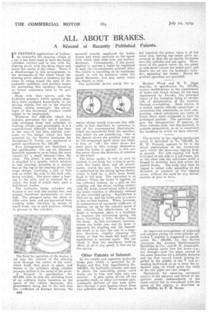
The particular device which this in venter claims would overcome this difficulty is best described by reference to one of the accompanying illustrations, which are reproduced from the specification which we are considering. One of the figures shows the position taken up by the component parts when the brake is free, or 'off ; the other shows the same parts as they arrange themselves when the brake is applied; in this ono the arrow shows the direction of rotation of the wheel.
The brake spider, it will at orte be; noticed, is not, fixed, but is free to move, with the brake shoes and all attach_ments, round the axle. Its movement is restrained by the strong spring shown, which is held by a shortlever firmly fixed to the axle. The operation is as follows: When the brake is applied, in .the orthodox fashion, by a pull on the coupling rod, the shoes, making contact with the drum, travel round with it until the brake reaction is effectually resisted by the extended spring. Equilibrium is then set up, and the brake acts in a. more or less normal fashion. When, however, in consequence of increased coeffieient of friction, set up by the reduced speed of the vehicle, the effectiveness of the brake is increased, there is a tendency to lengthen the restraining spring, the shoes travelling a little farther round the drum. As this movement, however, .causes the brake cam and ifs lever to approach the coupling red, the immediate result is to turn the cam in a negative direction, slightly releasing the brake, so that the,.shoes fall back ,until equilibrium is restored again. The net result is that t.he maximum braking effort, at all or any speed, is that set by the spring.
Other Patents of Interest.
In the simple and ingenious hydraulic brake gear which is patented by D. Napier and Son, Ltd. (specification No. 198,007), the hydraulic cylinder and that in which the controlling piston valve works are in line, and open into one another. A gear pump driven off the propeller shaft, or other convenient part, constantly delivers oil into both cylinders through a port located where those two cylinders meet. When the brake is
not required the piston valve is at the other end, ;leaving the outlet ports uncovered, so that the oil merely circulates into the cylinder-and out again. Movement of the ,piston valve—by the pedal or -side lever—closes the outlet port, and directs the oil into the hydraulic cylinder, operating the brake. Means for gradual operation are provided.
, —
Herbert Wood and H. P. Alger' describe, in specification No. 197,991, -certain modifications in the constituents of brake and clutch linings (of the typo represented by •Ferodo), the principal object of the invention being to obviate risk of deterioration, of the material
through overheating. Such fabrics,, it is stated, usually embody caoutchouc, or caoutehouc-like substances, in their cornposition, which substances are liable to break down when subjected to heat fOr prolonged periods. The patentees suggest the incorporation of pumice, or other volcanic rock, into the material, in suitable proportiona, so as to counteract the tendency to which we have referred.
The novelty in the tipping mechanism which is described in No. 198,153, by H. W. Piekard, appears to lie in the detail construction of the framework upon which the three-way tipping body is erected, For side tipping the body is hinged at one side to a sub-frame, but at the other side the sub-frame itself is hinged to stretcher bars laid across the chassis frame. The body may thus be tipped to either side, according to the direction of rotation' of the tipping screw, without theneed for any disconnection of pins or bolts.
An improved arrangement of induction and exhatist piping for twin-cylinder aircooled V engines' is suggested in Specification No. 198,200, by , the . Soeiete Armnyme des Amiens Etablisse.ments Hotchkiss et Cie., and H. M. Ainsworth. The exhaust ports face the front—i.e., the draught—rind the pipes extend in the same direction for a suitable distance and are then curved round, joining together in the middle of the V and extending backwards so as to cross the induction pipe, at which point the walls of the two pipes are cast integral.
Mechanism for ensuring automatic control of the advance and retard of the ignition point, independently of the hand control but in accordance with the speed of the engine, is described in No. 19%014, by F. H. Royce.