


Patents Completed.
Page 32
If you've noticed an error in this article please click here to report it so we can fix it.
Complete specifications of the following patents will be sent to any address in the United Kingdom by the Sales Branch, Patent Office, Holborn, W.C., upon receipt of eightpence per copy.
A Thornycroft Transmission Gear.
John I. Thornycroft and Co., Ltd., and H. Niblett, No. 24,226, dated 23rd October, 1912.—This invention relates to transmission gear in which the propellershaft is above the live axle. The particular feature of the construction is that the
axle-easing has a skeleton portion which embraces the gear-casing of the kind used with propeller shaft drive. The ordinary tubular part. of the axle-casing is provided with an intermediate ring-shaped portion which receives the curved part of the gear-casing ; in the construction illustrated these parts are cylindrical, and the casing is mounted by bolting the ring-shaped part to a flange on the casing. The drive is transmitted through a bevel-pinion and gear-wheel, and then through a single spur-gear reduction to the differential. Various modifications are described in the specification.
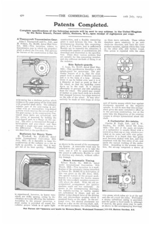
Radiators for Heavy Vans.
H. Windhoff, No. 17,321/12, dated under International Convention 25th July, 1911.—It is desirable to keep the construction of the radiator on a van as light as possible, in order that it may get rid of its heat quickly. Difficulty is experienced, however, in heavy vans which are stiffly sprung, owing to the vibration seriously affecting the radiator. According to the present invention, a stout casing is provided all round the radiator proper which is of quite light construction, and a flexible connectingpiece is used between the two. In the accompanying drawing this connecting. piece is of TJ-section, and is sufficiently flexible not to transmit the vibration; a considerable number of modifications are described and illustrated in the specification. These show various sections that are suitable for this connecting member, and also different methods of fixing it on the radiator.
Side Splash-guards.
C. Lean, No. 12,157, dated 22nd May, 1912.—This specification describes a siae splash-guard for motorvans. The particular feature of it is, that the mudguard itself is made of flexible material and is in the form of a loop. Alternatively it can be folded over, and it is of a diameter at least as great as that of the wheel, so that the mud-flap comes down on to the road. It is claimed effectually to prevent any side splashing from the wheel. The guard may consist of leather or some hard cloth in a double fold clamped between two rings mounted on the side of the wheel. It may alternatively be made of wire loops or strips as shown in the second of the accompanying figures. A removable tread may be attached to the guard so as to take the wear, and it will be appreciated that the guard is sufficiently flexible to yield on meeting any obstacle, without suffering damage.
;Bosch Automatic Timing.
Robert Bosch, No. 4693/13, dated under International Convention, 14th March, 1912.—This invention is a modification of the automatic timing described in Patent No. 24,665/12 (a description of this was given on the 5th June, 1913). The special feature of the present modification is to arrange the inertia masses and the intermediate members symmetrically about the shaft. With the old unsymmetrical arrangement the ignition machine could not run uniformly. AS shown in the accompanying drawings, the radially-moving or inertia masses are cylindrical in shape, and act on similar wedge-shaped faces of the driving disc and intermediate member which is mounted freely on the shaft. In the sectional view, the shaded abutments are fixed on a disc on the driving-shaft, and, as the speed increases, thy rollers bearing
on them move outwards. These rollers therefore move relatively in an anticlockwise direction, and force the intermediate member, against which they bear on the other side, still further round. This action is repeated with the other pair of inertia masses which bear against abutments mounted on the magneto spindle. It will be seen that this arrangement gives the same cumulative effect as in the previous construction, but at the same time the disposition of the rotating masses is always symmetrical about the shaft.
A Carburetter Air-intake.
Charles H. Pugh, Ltd.. and E. W. Starkey, No. 13,064, dated 4th June, 1912.—The end of the main air-intake of a carburetter is usually fitted with a screwed-on dust-cap or ring, which is provided at its outer end with wire gauze. In practice it is found that this gauze soon becomes choked with dirt, and this interferes with the free entry of air, and spoils the correct working of the carburetter. According to the present invention, the air-cap comprises a sleeve of wire gauze which takes air in at the end and also all round the aides. Preferably a strong cylindrical casing is provided, and the gauze is fixed inside it, although if desired, the gauze alone may be used, as shown in the accompanying drawings.