


Twin Wheel Incorporating
Page 34
If you've noticed an error in this article please click here to report it so we can fix it.
A Resume of
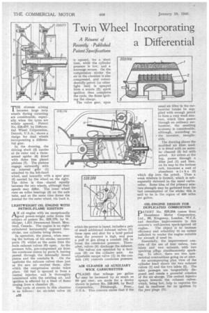
Recently Published a Differential THE stresses arising J. between large twin wheels during cornering are considerable, especially when the tyres are widely spaced. Patent No. 529,077, by Differential Wheel Corporation, Detroit, U.S.A., shows a design for dual wheels incorporating a differential gear.
In the drawing, the driving shaft (2) carries at its outer end a threearmed spider (6) fitted with three free planet pinions (7). The pinions engage outwardly with an internal gear (1) attached to the left-hand wheel, and inwardly with a spur gear (5) carried by the wheel on the right.
The drive is thus shared equally between the two wheels, although their speeds may differ. The inner wheel runs on roller bearings (3) on the axle tube, and at the same time forms the journal for the outer wheel, via bush 4.
LIGHTWEIGHT OIL ENGINE WITH PETROL-FLAME IGNITION
AN oil engine with anexceptionally good power-weight ratio forms the subject of patent No. 528,170, by W. Harper, 1,521 Drummond Street, Mon-. treat, Canada. The engine is an eightcylindered horizontally opposed twostroke, one cylinder being shown. •
In operation, the piston, when nearing the bottom of the stroke, uncovers ports (8) whilst at the same time the Main exhaust valves (6) open. As the pressure falls, pre-compressed air from the crankcase enters by ports 8, having passed through the internally finned piston and the conduits 9. On the upstroke the exhaust valves close just as the new air reaches them, after which the compression stroke takes place. Oil fuel is sprayed in from a central injector, and is thoroughly intermixed with the swirling air, and ignition is effected by a blast of flame issuing from a chamber (3).
The cycle of events in this chamber is as follows; An air-inlet valve (4) which the patent is based, includes a pair of small additional exhaust valves (7); these open and shut for a brief period when the pressure is high, and pass a puff of gas along a conduit (10) to boost the crankcase pressure. Thereafter, valves (6) discharge the exhaust. The valves are operated by a face cam (5) on the cylinder axis. An adjustable escape valve (1) in the conduit (10) controls crankcase pressure.
AIR CLEANER AS AUXILIARY WICK CARBURETTER
1--,LA1MS that mileage per gallon may be increased by as much as 50 per cent, are made for a device shown in patent No. .529,008, by Bocjl
Corporation, Pittsburgh, Penn., U.S.A. This concern states that if the usual air filter in the carburetter intake be supplied with enough petrol to form a very weak mixture, which then passes through an ordinary carburetter, the resulting economy is considerable, although, according to r the inventor, inexplicable.
The drawing shows the modified air filter used; it is fitted with an annular channel (3) fed with petrol. Air enters at the top, passes through a filter pad (1) and then, on its way to the bottom exit, traverses a nest_ of absorbent wic ks (2) which dip into the petrol. Thus a weak mixture is formed, which is subsequently richened in the usual carburetter. Some idea of the primary mixture strength may be gathered from the fuel consumption of the wicks; this is said to be in the region of 400 miles per gallon.
OIL-ENGINE DESIGN FOR DUPLICATED COMBUSTION
PATENT No. 528,584 comes from Ilesselman Motor Corporation, Ltd., 56, Kingsway, London, W.C.2, and describes improvements in this concern's well-known spark-ignited oil
engine. The object is to increase efficiency and reliability to an extent sufficient to render the engine suitable for aircraft if need be.
Essentially, the improvement consists of the use of four valves, two inlets and two exhaust, with two sparking pldgs simultaneously sparking. In effect, there are two symmetrical combustions going on at once.
An accompanying plan view of the cylinder head shows the two exhaust valves (1) and the two inlets (2). The inlet passages are tangentially disposed and create a powerful rotation of the air charge. The central injector sprays towards the exhaust valves, which, being hot, help to vaporize the fuel in readiness for its ignition by the .two plugs (3).