


PATENTS SUMMARIZED.
Page 24
If you've noticed an error in this article please click here to report it so we can fix it.
-A New Shock Absorber for Heavy Vehicles.
A shock absorber which provides for the relief of a heavy shock which is appli.d to one spring, by transmitting a part of it to the spring on the opposite side of the chassis, is illustrated below.
Semi-elliptic springs are anchored to the frame at their front ends. At the rear, instead of the usual dumb,irops, short levers carry the shackles, and each of the levers is keyed to its own cross shafts. The inner end of each cross shaft carries a lever, the oscillation thereof being restrained by a volute spring bearing against a sliding head which is Common to the two springs. Movement of the sliding head is limited by a couple of springs, the tension of which is adjustable.
-Light shocks on either side affect only the spring on that side. A heavy idiock acts on the sliding head, moving the main spring and allowing 'the half-elliptic roa'd spring on the opposite side to 'flex in unison.
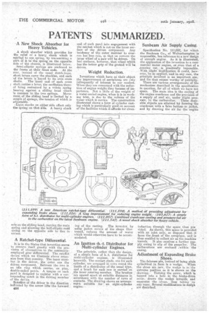
A Ratchet-type Differential.
It is in the States that invention seems to concern itself greatly with the provision of alternatives to the commonlyemployed gear differential: The. ratchet device which we illustrate above emanates from that country. The inner mem
, ber is the -driver, . the outer one the•driven component. Between the two is
an idle ring which carries, on pins, driuble-ended pawls. A tongue on each pawl is designed to register with a corresponding notch in the driving member of the device.
Rota tjon of the driver in the direction indicated by the arrow lifts the forward . li/V3
end of each pawl into engagement with the ratchet which is cut on the inner surface of the driven component. Any tendency of the outer member to overrun has free rein, so that on corners the inner wheel of a pair will be driven. On baAl surfaces, however' that wheel whiCh has the better grip of the ground will be driven.
Weight Reduction.
Inventions which have as' their object the improvement of aerdplanes are only infrequently of interest to our readers. When they are concerned with the reduction of engine weight they -become of importance. Not a little of the weight of a water-cooled engine, when it is in working trim, is due to the volume of the water which it carries. The construction illustrated shows a form of cylinder casting which is particniarly good on account of the facilities which it affords for clean • in of the casting. The inventor, by using jacket covers of the shape illustrated, reduces the amount of water which would otherwise have to be accommodated.
An Ignition -111.-t. Distributor for Multi-cylinder Engines.
The principle, rather than the design, of a simple form of 13..4. distributor for multi-cylinder engines, is illustrated herewith. The contact studs, one for each cylinder, are arranged in TOWS round the inside of a distributor of the usual type, and a brush for each row is carried on the inner rotatine. member. The brushes are spaced apart at suitable distances in accordance with the number of rows of contacts. The drawing shows an arrangement suitable for an eight-cylinder engine. Sunbeam 'Air Supply Casing.
Specification No. 111,057, for which the Sunbeam Co., of Wolverhampton is responsible, has reference to a new design of aircraft engine. As it is illustrated, the application of the invention to a commercial motor engine, or even that of a .touring car, _ is practically impossible. With slight modification it could, however, be so applied; and in any case, the principle involved is an important one, and for that reason worthy of publicity.
• There are various arrangements of the mechanism described in the specification in question, for all of which we have not space. The main idea is the cboling. of the engine crankcase and the provision of a supply of cool air, under slight piessure, to the carburetter. • These 'deeirable objects are attained by forming the crankcase with a false bottom or.jacket, and by drawing the air for the engine induction through the space thus pro vided. As shown, this space is provided with an inlet only, so disposed that. it faces the 'front of the aeroplane, and is thus enabled to collect air as the machine travels. It also receives a further supply owing to slip of the propeller. The carburetters are enclosed .within the
casing. .
Adjustment of Expanding Brake Shoes. The fulcrum pin, instead a being plain cylindrical in term is a wedge. When the shoes are new, the wedge isin. the extreme position as it is shown on the drawing: Turning the screw, which is tapped into a hole in the brake-drum cover, draws the wedge inwards, and separates the shoes, thus taking -up . any Wear. Several modifications in design are described.