


Patents Completed.
Page 26
If you've noticed an error in this article please click here to report it so we can fix it.
ANTI-SKID DEVICE.—Worby Beaumont,—No. 26,343, dated 18th December, l905.—At the side of the tyre a flap of
flexible material (13) is secured, having an enlarged tread or bead (8). Within this bead portion a wire or chain (c) may be secured, and fastened thereto are a. seriee of gripping devices (c). The flap is of such length that when the wheel is run fling normally the tread portion of each flap runs upon the road surface, whilst the connecting part hangs loose. As soon as skidding occurs, the devices (c) grip the road, and the tyre (A) advances on to the bead (b), which thus serves as a stop and prevents further lateral movement.
CONTROL DEVICE FOR ELECTRIC CARS.—Stevens.—No. 13,90:3, dated 18th June, 1906.—This device is adapted for uso with a vehicle wherein an engine (a) drives a dynamo (I?), and thus supplies motors (s f) with current whereby the road wheels of the vehicle are driven. The controlling device comprises a pedal (i), which is operatively connected with a re sistance switch (II). As the pedal is depressed more resistance is introduced into the circuit, until the circuit is broken, when still further movement of the pedal applies the baud brakes (a). Connected with the pedal is a catch (o), which enters notches in discs tk and I), respectively carried on the steering pillar and operated by handles (it and k L). The disc k is con. nented by a rod ()) to a controlling switch, whereby the windings of the dynamo may be thrown into series or parallel whilst the disc I is connected to the reversing switch. As the catch (o) drops into the notches in these two discs, it is impossible to operate either the controller or the reversing switch without first depressing the pedal so far that the current is entirely cut oft. This prevents sparking within the controller and accidental reversing When running full speed ahead.
FRICTION CLUTCH.— Serex. — 14,691 of 1906 (dated under Conventioni, 28th June, 1906.—To provide a gradual application of the clutch, the male mem
her (3) has a part of its periphery cut into tongues or strips (a), and these tongues are normally forced forward by springs kr). The leather (8), constituting the engaging surface of the clutch, extends over the tongues so that a continuoue engaging eutht ee is provided, and it will be seen that as the clutch comes into engagement under the action of the spring (5) that part of the leather which covers the tongues (a) first comes into contact with the opposing clutch member (1). The spring )5) is sufficiently strong to overcome the pressure of the springs (7) so that the tongues (a) are finally forced back, and the whole clutch surface engages in the usual manner. Adjust. ment for wear may be effected by nuts (10), which limit the advance of the tongues (a) under the action of their springs. Any number of tongues may be provided.
SPARKING PLUG. — Sharpe. — No. 3,402, dated 12th February, 1906.—Where it is desired to use an ignition plug, sometimes with accumulators and at other times with a magneto machine, difficulties are found to arise from the fact that the spark gap is not suitable for both purposes.
According to this invention, the porcelain body (a) of the plug has embedded in it two separate wires (d), one connected with a terminal tb) and the tither with a terminal (c). The sparking gap between the end (e) of one wire and the earthed member (,ea is less than that between the end (i) of the other wire and the earthed member, so that the live wire can be connected to either the terminal (LI or (el, according to whether a emelt or large spark gap is required.
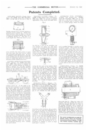
AUTOMATIC FUEL CONTROL.— Trotman and another.—No. 25,576a, dated 8th December, 1905.—On an iron core (E) a coil (1') is wound, and one end is connected with a contact device (K) on a eteam gauge, whilst the other
end is earthed through a suitable source of electric supply. The pointer (G) of the pressure gauge comes into confect with the device (K), and when this takes place, the coil (F) is excited and the core (E) magnetised. The inlet (C) for the fuel is carried through the core ,,E), and beneath the core is an armature (D). When the core is magnetised, the armature is drawn un against the end of the same, end thus closet the inlet (C) and cuts off the supply from the outlet (Cll. In thde armature is an orifice (DI), which may be regulated by a screw (D4) to serve as a by-pass if desired.
LUBRICATOR.—TiIston.--No. 23,859, 20th November, 1905.—The axle, or driving shaft (A) has an eccentric (I) mounted thereon, conveniently in proximity to the bearing. A spring-controlled plunger (G) bears against the eccentric (I). The plunger is hollow, and communicates with an oil bath (1) by an orifice (Cl): Communicating with the space below the plunger is one end of a conduit (J), whose other end (M) communicates with the bearing above the axle (A). When the orifice (G1) registers with the oil-bath the space beneath the plunger fills with oil, and, as the plunger descends, this is forced up through the conduit (J) to the upper portion of the bearing, whence it circulates back through the bearing to the oil-bath. The plunger (G) is made to serve as a sliding valve, whereby return of the lubricant through the conduit (j) is prevented.