


Slide Valves.
Page 23
Page 24
If you've noticed an error in this article please click here to report it so we can fix it.
Contributed by an Engineer-in-Charge.
The action of slide-valves in steam engines requir, to be thoroughly understood to obtain the best results trom them.
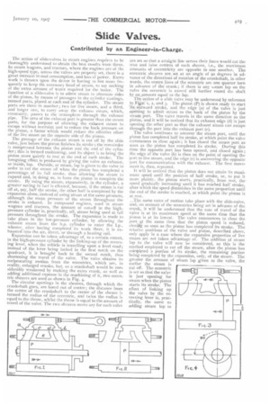
In steam wagons, and tractors, where the engines are of the high-speed type, unless the valves are properly set, there is a great increase in coal consumption, and loss of power. Extra work is thrown upon the driver in having io tire more fre quently to keep the necessary head of steam, to say nothing of the extra amount of water required for the boiler. The function of a slide-valve is to admit steam to alternate sides of the piston, by means of passages in the cylinder castings, termed ports, placed at each end of the cylinder. The steam ports are three in number ; two for live steam, and a third, and larger one, to carry away the exhausc steam, which, eventually, passes to the atmosphere through the exhaust pipe. The area of the exhaust port is greater than the steam ports, for the purpose of allowing the exhaust steam to escape without restraint and to reduce the back pressure on the piston, a factor which would reduce the effective effort of the live steam on the opposite side of the piston.
The passage of the exhaust steam is cut off by the slide valve, just before the piston finishes its stroke; the remainder is compressed between the piston and the end of the cylinder; this is termed cushioning, and its object is to bring the piston more quietly to rest at the end of each stroke. The foregoing effect is produced by giving the valve an exhaust, or inside, lap. Outside, or steam, lap is given to the valve in order to cut the steam off when the piston has completed a percentage of its full stroke, thus allowing the steam to expand and, in doing so, to force the piston to complete the stroke. By using the steam, expansively, in the cylinder, a greater saving in fuel is effected, because, if the steam is cut off at, say, half the stroke, the other half is completed by the expansion alone, instead of using steam at the same pressure, although the mean pressure of the steam throughout the stroke is reduced. In compound engines, used in steam wagons and tractors, the amount of cut-off in the highpressure cylinder is, practically, nil, steam being used at full pressure throughout the stroke. The expansion is made to take place in the low-pressure cylinder, by allowing the exhaust steam from the h.p. cylinder to enter the 1.p., whence, after having completed its work there, it is exhausted into the air, direct, or through a healing coil. Expansion can be taken advantage of, to a certain extent, in the high-pressure cylinder by the linking-up of the reversing lever, when the vehicle is travelling upon a level road; instead of the lever • being locked in the first notch on the quadrant, it is brought back to the second notch, thus shortening the travel of the valve. The valve obtains its reciprocating motion from the eccentrics, which are, in reality, enlarged cranks, but, as a crankshaft would be considerably weakened by making the extra crank, as well as adding additional expense in the machining of it, two eccentric sheaves are used as shown in Fig. 4. The circular openings in the sheaves, through which the crankshaft goes, are bored out of centre ; the distance from the centre of the crankshaft to the centre of the sheave is termed the radius of the eccentric, and twice the radius is equal to the throw, whilst the throw is equal to the amount of travel of the valve. The two sheaves neces!_arv for each valve are set so that a straight line across their faces would cut the true and false centres of each sheave, i.e., the maximum amounts of eccentricity are opposite to one another. The eccentric sheaves are set at an angle of 90 degrees in advance of the directions of rotation of the crankshaft, in other words, the centre lines of the eccentric arc one quarter turn in advance of the crank ; if there is any seam lap on the valve the eccentric is moved still further round the shaft by an Amount equal to the lap. The action of a slide valve may be understood by reference to Figs. 1, 2, and 3. The piston (P) is shown ready to start its outward stroke, and the edge (a) of the valve is just opening to admit steam to the back of the piston by the steam port. The valve travels in the same direction as the piston, and it will be noticed that its exhaust edge (d) is just opening the other port so that the exhaust steam can escape through the port into the exhaust port (e). The valve continues to uncover the steam port, until the piston has completed half its stroke, at which point the valve commences to close again ; it has closed the steam port as soon as the piston has completed its stroke. During this time the opposite port has been opened, and closed again ; the edge of the valve (b) is then on the point of opening the port to live steam, and the edge (c) is uncovering the opposite port for communication with the exhaust. The first movement is, then, repeated.
It will be noticed that the piston does not attain its maximum speed until the position of half stroke, or, to put it more plainly, the piston starts, practically, from rest, the speed gradually increasing until it has reached half stroke, after which the speed diminishes in the same proportion until the end of the stroke is reached, at which point the piston is at rest.
.._The same rates of motion take place with the slide-valve, and, on account of the eccentrics being set in advance of the crank, it will be understood that the rate of travel of the valve is at its maximum speed at the same time that the piston is at its lowest. The valve commences to close the portat the same time that the piston speed is reduced, closigg as soon as the piston has completed its stroke. The relative positions of the valve and piston, described above, only apply in a case where the expansive properties of live steam are not taken advantage of. The addition of steam lap to the valve will now be considered, as this is the method employed to cut off the steam, after the piston has rompleted a portion of its stroke, the remaining portion being completed by the expansion, only, of the steam. The greater the amount of steam lap given to the valve, the earlier the steam is cut off. The eccentric is set so that the valve is just opening for steam when the piston starts its stroke. The effect of linking up the valve by the re versing lever is, practically, the same as adding steam lap to the valve, causing it to open later at each end by slightly reducing the travel, owing to the die block being brought nearer to the centre of the link. The addition of too much steam lap in conjunction with excessive linking up causes "wire-drawing," i.e., the steam cannot enter the cylinder fast enough to exert its proper pressure upon the piston. The effect of adding exhaust lap to the valve is to cut off the exhaust earlier, before the piston has completed its stroke; the piston has, then, to compress the steam remaining in the cylinder, and this causes the piston to be cushioned at the end of each stroke, although, if too much exhaust lap is allowed, the port is closed too soon and big back pressure is set up, with a consequent loss of power. Steam lap means the extent to which the valve overlaps the edges of the steam ports, when the valve is in mid position, whilst the exhaust lap is the amount that the edges of the valve overlap the ports on the inside.
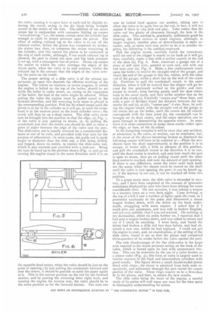
The proper setting of a slide valve is of the utmost importance, as upon this depends the efficient working of the engine. The valves on tractors, or steam wagons, in which the engine is bolted on the top of the boiler, should be set while the boiler is under steam, as, owing to the expansion of the boiler, the lead of the valve might be affected. When setting the valve the engine must be pulled round in the forward direction, and the reversing lever must be placed in the corresponding position. Pull the fly-wheel round until the piston is as far in the cylinder as it will go, or until the crosshead is at the nearest point to the front cylinder cover ; the crank will then be on a dead centre. The slide valve must now be brought into the position so that the edge, (a) Fig. 1, of the valve is just opening to steam, or, by pulling the crankshaft just over the centre you should be able to enter a piece of paper between the edge of the valve and the port. The slide-valve rod is usually screwed for a considerable distance at one of its ends, and provided with four nuts for the purpose of adjustment : in some cases, the guide rod is made larger in diameter than the slide rod, a hole being drilled, and tapped, down its centre, to receive the slide-valve rod, which is also screwed and provided with a lock-nut. Bring the nuts by hand up to the position shown (Fig. 1), and go on turning the engine round in the same direction until it is on now be locked hard against one another, taking care to allow the valve to be quite free on the rod, in fact, it Will not matter if there is 1-64 inch end play. Take notice that the valve rod has plenty of clearance through the hole in the slide valve. This method is, practically, sufficiently good for locating the dead centres in small engines, although, in Larger engines, another plan of determination is more accurate, and, as some men may prefer to do it in smaller engines, the following is the method employed.
Pull the engine round, carefully watch the cross-head, until the end of the clipper is nearly as far back as it will go, then, carefully, make a line with a scriber exactly at the end of the shoe (a), Fig. 6. Now, construct a gauge out of a piece of stiff steel wire, pointed at each end, and with one end bent over (e), Fig. 6. Make a fine centre-punch mark upon the boiler, to receive the straight end of the gauge, and insert the end of the gauge in this dot, whilst, with the other end of the gauge, scribe a short line on the web of the crank (b). Continue to pull the crankshaft round, in the same direction, when it will be noticed that the slipper will go beyond the line previously scribed on the guides and commence to return; keep turning gently until the shoe comes back to the same mark, and then scribe another line on the web of the crank (c). Carefully "centre pop" these lines, and with a pair of dividers bisect the distance between the two marks (b) and (c), at (d); "centre pop" d also. Now, by pulling the engine round, with the straight end of the gauge in the centre dot on the boiler, until the centre dot (4) exactly corresponds with the bent point (e), the crankshaft can be brought on its dead centre, and the same operation can be gone through in determining the opposite centre. In some cases it is more convenient to make these marks either upon the edge, or face, of the fly-wheel.
In the foregoing remarks it will be clear that any accident, or alteration, to the valve, or motion, can be overcome, but, in the event of the sheave becoming broken or displaced the following course will have to be resorted to :—Place the new sheave upon the shaft approximately in the position it is to occupy, or better still, a little in advance of this position, and pull the crankshaft round in the direction it is to run, until the dead centre is reached, and note how much the port is open to steam, then go on pulling round until the other dead centre is reached, and note the amount of port opening. If there is any difference, move the valve until both leads are the same, when the sheave must be moved on the shaft until the valve is just Opening the port ; it can be keyed up, or, if the keyway is not cut, it can be marked off from this position.
To a great many men, the slide valve is shrouded in mystery, and I have been surprised at the amount of ignorance sometimes displayed by men who have been driving for some considerable time. On one occasion, I was taking a wagon to a country town on a very dark night. Upon arriving at the top of a hill I saw a number of lights upon the road, so I proceeded cautiously to the point and discovered a steam wagon broken down, with the driver on his back underneath, struggling with some repairs. I asked him if I could give any assistance, and was told in broken English, and not very politely, that I was not wanted. On arriving at my destination, about six miles further on, I reported that I had seen a wagon broken down, and was asked to return and see if I could do anything. I went back, and found the driver bad broken a slide rod two days before, and had obtained a new one, which he had replaced. I could not get the engine to start, and, on examination, of the setting of the slide valve, found it set so that the piston had completed three-quarters of its stroke before the valve opened the port.
The only disadvantage of the flat slide-valve is the large area exposed to the steam pressure acting on the back of the valve, which is forced upon its face with unnecessary friction. This can be overcome by the use of a valve known as a piston valve (Fig. 5); this form of valve is largely used in marine engines in the high and intermediate cylinders with good results. The figure shows a small double-ended piston fitted with rings ; the steam is admitted from both ends respectively, and exhausted through the port round the centre portion of the valve. These rings require to be a first-class fit in the piston, and bore, to obtain the best results. The slide valve being the heart of the engine, a careful study of its action will well repay any man for the time spent in thoroughly understanding its action.