


A Portable Suction-Gas Producer.
Page 22
If you've noticed an error in this article please click here to report it so we can fix it.
A suitable design for a small, portable, and efficient gasproducing plant, which could be applied to public-service vehicles, or to goods lorries, has been wanted for some time. No really practical form of apparatus has, up to the present, been introduced, because the difficulties in the way of the invention of a plant that would prove at once compact, low in weight, and reliable, have seemed insurmountable.
Mr. Vaughan Williams, of 14, Great James Street, Bedford Row, W.C., to whose experiments we made sante references in our issue of the 23rd August last, has invented
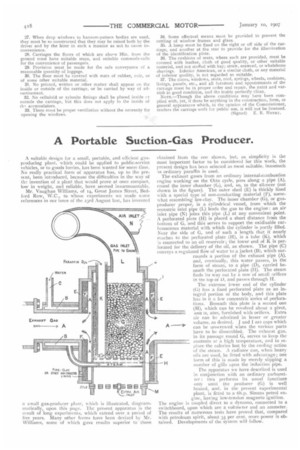
a small gas-producer plant, which is illustrated, diagrammatically, upon this page. The present apparatus is the result of long experiments, which extend over a period of live years. Many other forms have been devised by Mr. Williams, some of which gave results superior to those obtained from the one shown, but, as simplicity is the most important factor to be considered for this work, the present design has been selected as most suitable; inasmuch is ordinary paraffin is used. The exhaust gases from an ordinary internal-combustion engine working on the Otto cycle, pass along a pipe (A), round the inner chamber (G), and, so, to the silencer (not shown in the figure). The outer shell (E) is thickly lined with a special type of non-conducting material (F), somewhat resembling lire-clay. The inner chamber (G), or gasproducer proper, is a cylindrical vessel, from which the eccentric inlet pipe (L) leads the gas to the engine an air inlet pipe (N) joins this pipe (L) at any convenient point. A perforated plate (H) is placed a short distance from the bottom of G, and this serves to support the oxidisable carbonaceous material with which the cylinder is partly filled. Near the side of G, and of such a length that it nearly reache3 to the perforated plate (H), is a tube (K), which Ls connected to an oil reservoir; the lower end of K is perforated for the delivery of the oil, as shown. The pipe (C) conveys a regulated flow of water to a jacket (B), which surrounds a portion of the exhaust pipe (A), and, eventually, this water passes, in the form of steam, to a pipe CD), carried beneath the perforated plate (II). The steam finds its way out by a row of small orifices in tne top ot 13, and passes through H.
The extreme lower end of the cylinder (G) has a fixed perforated plate as an integral portion of the body, and this plate has in it a few concentric series of perforations. Beneath this plate is a second one (M), which can be revolved about a pivot, aria is, also, furnished with orifices. Extra air can be admitted in lesser or greater volume, as desired. J and I are caps which can be unscrewed when the various parts have to be dissembled. The exhaust gas, in its passage round G, serves to keep the contents al: a high temperature, and to replace the calories lost by the cooling action of the steam. A radiator can, when heavy oils are used, be fitted with advantage; one form of this is made by merely slipping a number of gills upon the induction pipe.
The apparatus we have described is used in conjunction with an ordinary carburetter : this performs its usual functions only until the producer (G) is well heated, and, in the present experimental plant, is fitted to a 6h.p. Simms petrol en gine, having low-tension magneto ignition. The engine is coupled direct to a dynamo, connected to a switchboard, upon which are a voltmeter and an ammeter. The results of numerous tests have proved that, compared with petroleum spirit, about 35 per cent. more power is obtained. Developments of the system will follow.