


Hydraulic Ejector for Refuse Collectors
Page 40
If you've noticed an error in this article please click here to report it so we can fix it.
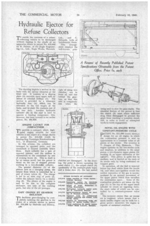
enable the contents of a refuse collecting vehicle to be discharged without tipping is the objet of an apparatus shown in patent No. 515,642 by R. Palmer, of the Eagle Engineering Co., Ltd., Eagle Works, Warwick.
The drawing depicts a section of the body with the ejector retracted at the front end. It consists of a sloping plate (9) movable upon upper rails by means of wheeled, trolleys (1). The motion is .provided by a telescopic hydraulic ram (4) which can be extended to the full length of the body, and so push the contents out of the rear door. Another hydraulic cylinder (2) in the roof is used to operate a loading compressor; this, however, has been covered in an earlier patent, No. 484,826, ENGINE LAYOUT FOR COMPACTNESS proiride a compact. silent, high speed engine suitable for road vehicles is the object of a design shown in patent No. 513,032 (void) by Bussing-Nag Vereinigte Nutzkraftwagen A.G., of Brunswick, Germany.
In this scheme, the cylinders arc arranged in opposed pairs, and the crankshaft is located centrally below them. Each cylinder has a pair of opposed pistons, and the motion is transmitted to the crankshaft by sets of rocking levers (4). This in itself is by no means novel, but the patent is based on the use of stepped pistons working in a two-diameter cylinder.
The greater diameter (1) of the pistons acts as a charging pump, the output from which is controlled by a pair of rotary valves (5). The charge is fed to an inlet ring of ports (2), whilst the exhaust leaves via a similar ring (3). The silence of the engine is said to be due to the complete enclosure, not only of the working parts, but also of the air passages.
EASY CHANGE BY GEARBOX ISOLATION 'TO facilitate gear-changing by comI pletely isolating the gearbox is the object of a scheme shown in patent No. 515,538 by Shelvoke and Drewry.
A.30 clutches are disengaged. In the drawing, the pedal is shown operating the usual clutch (1), the output clutch (3) (preferably of the multiple-plate type) and a brake shoe (2), the last named being used to slow the gear-shafts. The essential feature of the patent is that the clutch (3) must retain sufficient drag when disengaged to prevent the gears from reaching a complete standstill, in order to avoid an attempted tooth-to-tooth engagement.
NOVEL OIL ENGINE WITH CONSTANT-PRESSURE CYCLE
PATENT No. 511,596 (void) shows a design for an oil engine in which the combustion pressure is said to approximate to a constant value at all points of the stroke. The inventor is T. Dragos, of Cluj, Rumania. This engine operates on the two-stroke cycle and employs, in addition to the usual piston, a two-diameter upper piston (3) working ii an 'upper extension of the
This piston is quite free to oscillate, and is limited at the ends of its stroke only by being cushioned on trapped gases.
In operation, all the fuel is injected before top dead centre from the nozzle (4), and when auto-ignition occurs the sudden expansion of the gas is accomtnodated by an upward movement of the upper piston which thus increhes the combustion space. Some of the combustion products are taken via the pipe (1) to the top of the upper small cylinder to create an opposing force, the exact value of which can be controlled by a constant-pressure valve (2).
The inventor claims that no excess air is required, which means that a much smaller engine can be built for a given power; moreover, the engine is capable of sustained overload.