


TRACTOR WHEELS.
Page 30
If you've noticed an error in this article please click here to report it so we can fix it.
A Resume of Recently Published Patents.
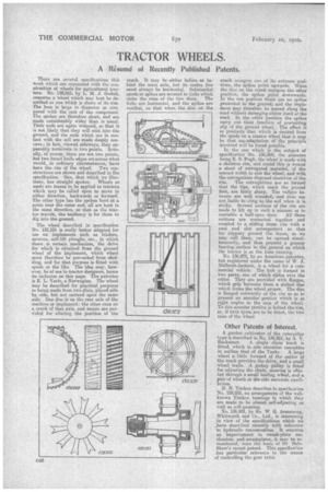
There are several specifications this week which are concerned with the construction of wheels for agricultural tractors. No. 128,952, by L. M. J. Godail, concerns a wheel which may best be described as one which is shorn of its rim. The boss is large in diameter as compared with the rest of the component. The spokes are therefore short, and are made considerably wider than is usual. Their ends are again widened, so that it is not likely that they will sink into the ground, and the ends which are in contact with the soil are made deeply concave; in fact, viewed sideways, they apparently terminate in two points. Actually, of course, there are not two points, but two broad knife edges set across what would, in ordinary circumstances, have been the rim of the wheel: Two constructiona are shown and described in the specification. One, that which we illustrate, has straight spokes. Wheels so made are meant to be applied to tractors which may be called upon to move in either direction, backwards or forward. The other type has the spokes bent at a point near the outer end, all are bent in the same direction, so that as the tractor travels, the tendency is for them to dig into the ground.
The wheel described in specification No. 132,531 is really better adapted for use on implements each as binders, mowers, self-lift ploughs, etc., in which there is certain mechanism, the _drive for which is obtained from the ground wheel of the implement, which wheel must therefore be prevented from skidding, and for that purpose is fitted with spuds or the like. The idea may, however, be of use to tractor designers, hence its inclusion on this page. The patentee is E. L. Varlo, a Norwegian. The wheel may be described for practical purposes as being made from two discs, placed side by side, but not centred upon the same axle. One disc is on the rear axle of the machine or implement: the other runs on a crank of that axle, and means are provided for altering the position of the
crank. It may be either before or behind the main axle, but its centre line must always be horizontal. Substantial spuds or spikes are secured to links which unite the rims of the two discs. The links are horizontal, and the spikes arc vertical, FO that when the disc on the crank • occupies one of its extreme positions, the spikes point upwards. When the disc on the crank occupies the other position, the spikes point downwards. In the one position there are no spikes presented to the ground; and the implement may therefore be moved along the road without damaging either itself or the road. In the other position the spikes carry out their _function of preventing slip of the ground wheel. The effect is so precisely that which is desired from the spuds on a tractor wheel that it may be that ane adaptation of :the principle involved will be found possible. In the one which is the subject of specification No. 136,869, the patentee being E. S. Pugh, the wheel is made with a skeleton rim, and round this is wound a sheet of corrugated material, of the correct width to suit the wheel, and with the corrugations disposed slantwise of the rim. The corrugations are so formed that the tips, which reach the ground first, are fairly sharp. The valleys between are well rounded, and thus are not liable to cling to the soil when it is sticky. Several sections of the rim are made to lift up in such a nianner as to resemble a half-open door. All these sections are connected together and coupled to a sliding inner rim with a cam and slot arrangement so that for slippery ground the doors, as we may call them, can be opened simultaneously, and thus present a greater bearing surface to the ground on which the tractor is at the time running.
No. 136,972, by an American patentee, hut registered under the name of W. J. Afellersh-Jackson, is a wheel for a commercial vehicle. The hub is formed in two parts, one of which slides over the other. They are provided with flanges, which grip between them a dished disc which forms the wheel proper. The disc is flanged outwardly at the rim so as to present an annular portion which is at right angles to the axis of the wheel. To this annular portion is bolted the rim, or, if twin tyres are to -be fitted, the two rims of the wheel.
Other Patents of Interest.
A garden cultivator of the caterpillar type is described in No. 136,951, by A. V. Rackstraw. A single chain track is fitted, which in side elevation resembles in outline that of the Tanks. A large wheel a little forward of the centre of the track provides the drive, and a small wheel trails. A jockey pulley is fitted for adjusting the chain, steering is effected through a small leading wheel, and a pair of wheels at the side maintain, equilibrium.
H. H. Timken describes in specification No. 129,255, an arrangement of the wellknown Timken. bearings in which they are made to be almost self-adjusting as well as self-securing. No. 136,931, by Sir. W. G. Armstrong, Whitworth and Co., Ltd., is interesting in view of the specifications which we ,.have described recently with reference to hydraulic transmissions. It concerns an improvement in awash-plate mechanism, and ewashplatee, it may be remembered, were the bas6 of Dr HeleShaw's recent patent. This specification has particular reference to the means of controlling the gear ratio.