


Steering, 2
Page 69
If you've noticed an error in this article please click here to report it so we can fix it.
IF SATISFACTORY steering and minimum tyre wear are to be achieved, various geometrical angles (alignment, camber, castor and kingpin inclinations) must be built into the steering system and maintained throughout the vehicle's life. Although these angles will not alter with ordinary driving, a heavy bump may derange them and a check should be made after even slight collisions.
When the vehicle is travelling straight ahead, the front wheels must be parallel and an allowance must be made for the essential slight clearance present in the steering joints. When the vehicle is moving forward, there is a tendency for the front wheels to splay out, taking up the play in the steering links.
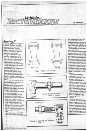
A small amount of "toe in" of the wheels when the vehicle is stationary is usually recommended so that they are parallel when the vehicle is being driven. Figure 1 illustrates "toe in" and "toe out".
Vehicle manufacturers specify the actual setting but somewhere between parallel and 4.5 mm (3/16in) is usual. The amount of toe in sometimes varies with the type of tyres fitted. For example, on the Ford Cargo fitted with cross-ply textile cord tyres the toe in is specified as 1.5 to 4.5 mm (0.06 to 0.18in) while 0.0 to 1.5 mm (0.00 to 0.06in) is recommended if radialply textile cord tyres are used.
Special gauges are available for checking wheel alignment
and these vary from a simple trammel to measure the distance between the wheel rii to elaborate optical gauges. Ti toe in is adjusted by altering if effective length of the track roc
On commercial vehicles witl beam axle this is a comparativelysimple procedu as one end of the track rod haE left hand thread while the othE end has the conventional right hand thread. To alter the wheE alignment it is only necessary slacken the locking arrangem( at each end of the track rod an then rotate the track rod until correct alignment of the whee is obtained. The track rod is located by clamps or by lockir nuts. The clamp type is showr Figure 2 and a locking nut in Figure 3.
On light vehicles with independent front-wheel suspension three track rods a generally used and if the adjustment is obtained by altering the length of the two outer track rods it is importar that they are lengthened or shortened an equal amount. I this is not done the Akermani effect on turns will be affecte Incorrect alignment will cal the tread of the tyres to wear down on one edge and a "feathering" effect will be noticed.
When checking wheel alignment, particularly after vehicle has been involved in collision, it is important to rn sure that the front wheels an not bent. It will be appreciatE that if a wheel is running a1A out of true, then measureme taken from the wheel rim col be incorrect by this amount.