


A Wheel-operated Hydraulic Pump
Page 60
If you've noticed an error in this article please click here to report it so we can fix it.
A &mime of Recently Published Patent Specifications
PATENT No. 606,128, comes from the Timken-Detroit Axle Co., Detroit, Michigan, U.S.A., and shows a scheme for operating trailer brakes with power generated by the wheels of the vehicle.
In this scheme, the tractor and trailer are provided with their own complete hydraulic braking systems. The two are, of course, interconnected either by a flexible pipe, or a Bowden cable, but this is in the nature of a control member, and does not provide the braking force. The latter comes from an hydraulic pump driven by the trailer wheels, and this unit is illustrated in the drawing. The tractor is also fitted with a similar unit, as the same methods are used on this also.
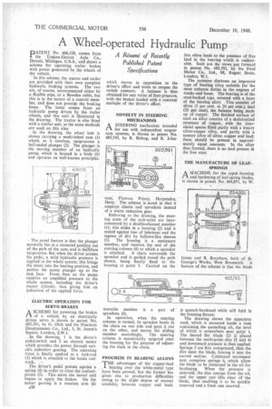
In the drawing, the wheel hub is shown carrying a multi-lobed cam (1) which, as it revolves, reciprocates a ball-ended plunger (2). The plunger is the moving member of an hydraulic pump, which is housed in a body (3) and operates on well-known principles.
The novel feature is that the plunger normally lies in a retracted position out of the path of the cam, and is theiefore inoperative. But when the driver presses his pedal, a mild hydraulic pressure is applied to the whole system; this brings the shoes into the bearing position, and pushes the pump plunger up to the Ca111 face. From then on the pump supplies an amplified pressure to the whole system, including the driver's master cylinder, thus giving him an indication of the applied force.
ELECTRIC OPERATION FOR SERVO BRAKES
A. SCHEME for powering the brakes of a vehicle by an electrically driven servo is shown in patent No. 605,391, by G. Olah and the Precision Developments Co., Ltd., 3, St. James's Square, London, S.W.1.
, In the drawing, 1 is the driver's pedal-switch and 2 an electricmotor which provides the power through suitable reduction gearing. The operating force is finally applied to a rack-rod (.3) which is attached to the brake rodWork. .
The driver's pedal presses against a spring (4) in order to close the contactpoints (5). This starts the motor and begins to apply the brakes. On the motor gearing is a reaction arm (6) A38 which moves in opposition to the driver's effort and tends to reopen the switch contacts. A balance is thus obtained for any value of foot-pressure, with the brakes loaded with a constant multiple of the driver's effort.
NOVELTY IN STEERING MECHANISMS
ASTEERING mechanism intended for use with independent suspension systems, is shown in patent No. 605,745, by R. Bishop, and R. John
ston, Flowton Priory, Harpenden, Herts. The scheme is novel in that it employs chains and sprockets instead of a worm reduction gear.
Referring to the drawing, the steering arms of the stub-axles are interconnected by a double-channel member (1); this slides in a housing (2) and is sealed against loss of lubricant and the ingress of dirt by bellows-like sleeves (3). The housing is a stationary member, and receives. the end of the steering column (4) to which a sprocket
is attached. A chain surrounds the sprocket and is guided round the path shown, being finally fixed to the housing at point 5. Carried on the movable member is a pair of sprockets (6).
In operation, when the steering column is turned, its sprocket hauls in the chain on one side and pays it out on the other, and moves the sliding member accordingly. The steering column is eccentrically spigoted onto the housing for the purpose of adjusting the slack in the chain.
PROGRESS IN BEARING ALLOYS
THE advantages of the copper-lead bearing over the white-metal type have been proved, but the former has given rise to production difficulties owing to the slight degree of mutual solubility between copper and lead;
this often leads to the presence of free lead in the bearing which is undesirable. Such are the views put forward in patent No. 605,593, by the Ford Motor Co., Ltd., 88, Regent Street, London, W.I.
The patentee discloses an improved type of bearing alloy suitable for the most arduous duties in the engines of trucks and buses. The bearing is of the steel-backed type, covered with a layer of the bearing alloy. This consists of silver (5 per cent. to 20 per cent.), lead (35 per cent), the balance being made up of copper. The finished surface of such an alloy consists of a skeletonized structure of copper, with the intersticial spaces filled partly with a binary silver-copper alloy, and partly with a ternary alloy of silver, copper and lead; these should be present in approximately equal amounts. In the alloy thus formed, there is no lead present in the free state.
THE MANUFACTURE OF LEAFSPRINGS
AMACHINE for the rapid forming and hardening of leaf-spring blades, is shown in patent No. 604,891, by W.
James and B. Brayshaw, both of St. George's Works, West Bromwich. A feature of the scheme is that the blade is quench-hardened while still held in the forming fixture.
The drawing shows the apparatus used, which is mounted inside a tank containing the quenching oil, the level of which is somewhere near. point 1. The heated flat blade (2) is placed between the multi-point dies (3 and 4) and downward pressure is then applied. Springs 5 are first compressed, then the dies meet the blade, forcing it into the curved outline. Continued movement next compress springs 6, which allow the blade to be immersed in the oil for hardening. When the pressure is removed, the dies emerge from the oil, and the upper one lifts clear of the blade, thus enabling it to be quickly removed and a fresh one inserted.