


Patents Completed.
Page 24
If you've noticed an error in this article please click here to report it so we can fix it.
DEVICE FOR SUPPORTING DETACHABLE R1MS.—Dunlop Pneumatic Tyre Company, Limited, and Another— No. 6,058, dated 18th March, 1908.—This device is for supporting a detachable rim when the latter is detached front the wheel in order to facilitate the removal of the tire. The device comprises three arms (A), each having at one end a clamp or saddle by means of which it is secured to the felloe (13) of the wheel. The clamp or saddle consists of three-jointed members la, al and a2), the member (al1) being screw-threaded and provided with a buttertly nut (a4). At the other end of the arms (Al is a recess (0) adapted to receive the detachable rim jCI, and an ad.
justable plate (a6) sliding in a slot (al) is provided in order to clamp the rim to the arm. The three arms (A) constitute a three-point suspension for the detachable rim, and the felloe (B) acts as a fulcrum for the said arms so as to enable them to he adjusted radially by the tightening or the slackening of the butterfly nuts (a4). Suspension at two diametrically-opposite points is an available alternative.
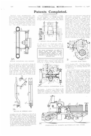
STEAM-DRIVEN VEHICLE.— Clarkson and Another. No. 16,598, dated 6th August, 1908.--The engine (H) drives, through differential gear and cardan shafts
(E), the pinions (CI which gear with internal teeth on rings (A1) secured to the thick) wheels. The casing (G, of the differential gear is provided with external teeth (G1) which engage with, and are driven by, a pinion on the crankshaft of the engine. A pinion (G2), fixed on the differential casing (G), gears with a spur wheel IK11 mounted on a shaft (K). This shaft is provided with eccentrics (1,, L1) which drive the feed-water pump and ti fuel pump respectively. A worm (K formed on the shaft (K) engages with worm wheel (M1) on a shaft (M) eaten ing, through the wall of a chamber (N) at is furnished with a worm. This worm e gages with a worm wheel (Ni) on spindle (N2) carrying cams (N3) adapt< to lift arms (N1) against the action springs (NI) and to allow them to retu: suddenly, thus forcing down the plung of a forte pump (P), and supplying lubi cant from the chamber (X) to the cyli der through the outlets (N6). It will I seen that the differential gear, the shad (K and 111 and the adjacent mechanis are all mounted in or on the casing I which is attached to the engine casing crank chamber (H1). Thus the whole t rangement is very compact and can read: be adapted to an existing chassis of t de Dion type.
SELF-PROPELLED FIRE ENGIN —Hudson.—No. 3,781, dated 19th Febi ary, 1908.—According to this inventi the boiler (Al is arranged at the rear the vehicle, while the propelling engi 113) is placed nearly midway of the chi sit. In the forepart of the vehicle arranged the pumping engine (C), wa: tank 'DI and hose box (El. The sNbetween the propelling engine (13) and I steam-pumping equipment (C) is of su an extent that it gives ready access either engine for cleaning, repacking, repairs. There is sufficient room for man to stand up between the two engin and this fact renders both engines v( accessible. It will be seen that the notal features of this arrangement are acces bility and even distribution of weight.