


Universal Semi-trailer Coupling Attachment
Page 34
If you've noticed an error in this article please click here to report it so we can fix it.
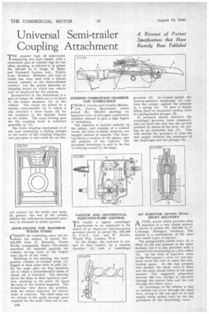
THEpopular type of semi-trailer employing two road wheels, with a retractable pair of wheeled legs for use when standing, is referred to in patent No. 522,461 by P. Hugh, H. Baker and Scammell Lorries, Ltd., Tolpits Lane, Watford. Hitherto, this type of trailer has been used with a special tractor (usually of the three-wheeled variety), but the patent discloses an adapting device by which any vehicle may be employed for the purpose.
Incorporated in the attachment is a pair of ramps (3) which are to be fixed, to the ...frame members (5) of the vehicle. The ramps are joined by a tubular cross-member (4) to which is also attached a short frame (2) for the reception of the foldable frame of the trailer. The usual locking gear for the coupling hook is indicated generally at (1). The brake coupling mechanism is of the type employing a sliding plunger in the centre of the coupling king-pin, and provision is also made for an elec
SNOW-CHAINS FOR MAXIMUMWIDTH TYRES CHAINS for combating snow and ice ....form the subject of patent No. 522,670 from D. Kennedy, Forest Works, Longparish, Hants. The chains described are intended specially for vehicles having tyres of the largest sizes (up to 15 ins. wide).
Referring to the drawing, the tread portion consists of twisted strips (1) hinged at their outer ends on pins (5). Onthe same pins are flap members (3) to which a circumferential series of chains (4) is attached. The drawing shows the flaps in their operative position, abutting at the point (2) upon• the ends of the twisted members. The dotted-line view shows the position, with the chains removed, for attachment or removal, The chief claim for the scheme is the small stowage space required for the outfit when not in use.
STEPPED COMBUSTION CHAMBER FOR TURBULENCE
FROM S. Crooke and Crossley Motors, Ltd., Gorton, Manchester, comes patent No. 522,313 showing an improved form of oil-enginecombustion chamber claimed to give a high degree of turbulence.
The chamber is located entirely it1 the piston, and consists of a conical recess, the sides of which, however, are stepped instead of smooth. The drawing shows a section of the piston, also the position of the injector. The increased turbulence is said to be due to eddying caused by the steps.
VACUUM AND CENTRIFUGAL INJECTION-PUMP CONTROL enable a lighter centrifugal 1 mechanism to be employed is the object of an improved injection-pump governor shown in patent No. 522,569 by C.A.V., Ltd., and W. Nicolls, Warple Way, London, W.3.
In the design, the rack-rod is subjec+ to dual control, by a vacuum chamber (2) and a centrifugal governor. (5). At normal speeds, the suction-operated diaphragm (1) controls the output, against the pressure of a spring (6). To give a steady idling speed at maximum suction there is a spring-loaded plunger (3).
At excessive speeds, however, the centrifugal governor takes command, and can move the rack into the no-fuel position by means of the lever (4) acting on an extensible link (7). This link enables the governor to close the fuel supply without the resistance of the diaphragm and the plunger (3).
AN INJECTOR GIVING DUALSPURT DELIVERY AFUEL nozzle which provides pilot injection in a very simple manner is shown in patent No. 522,666 by P. L'Orange, Stuttgart, Germany. The scheme is a combination of the open _ and closed types of injector.
The spring-loaded needle-valve (2) is lifted by the fuel pressure in the usual msimer, but it is also, provided with a central bore terminating in a fine orifice (3). At the start of injection, some of the -fuel passes a valve (1) and proceeds down the bore to enter the combustion space. As the fuel pressure rises further, the whole valve is lifted and the main charge enters in the usual manner. The suggested proportion between the two charges is one-sixth through the central bore and the rest through the lifted valve.
An advantage of the scheme is that dribble can occur through the small bore, owing to the last part of its fuel supply being sucked back by the displacement of the descending valve.