


INTENSIFYING THE SPARK.
Page 28
If you've noticed an error in this article please click here to report it so we can fix it.
A Resume of Recently Published Patent Specifications.
E°BERT VON LEPEL, of Berlin, in specification No. 238,505, describes what appears to be a very interesting' invention in connection with ignition. He says : "it is known that ignition failure in internal-combustion engines takes place very often because soot, ail, or moisture is deposited upon the surface of the intulator, of the sparking plug, or between the poles of the spark gap in the ignition plug, such deposit forming a shunt to the spark gap." He further points out that the portion of the current that passes through the shunt has the action of
ciminishing the ohmic resistance of the shunt, so matters get worse as time gees (n. The object of the invention is to reduce the risk of such a shunt forming and to provide a more useful form of spark.
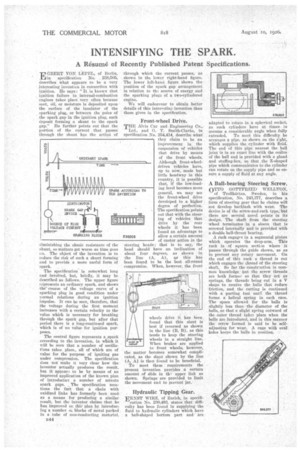
-The specification is somewhat long and involved, but, briefly, it may be described as follows. The upper figure represents an ordinary spark, and shows the course of the voltage curve of a sparking plug in good condition under normal relations during an ignition impulse. It can be seen, therefore, that the voltage during the first moment increases with a certain velocity to the value which is necessary for breaking thrOugh the spark gap, but after that period .there is a long-eontintied spark, which is of no value for ignition purposes.
The central figure represents a spark according to the invention, in wtich it will be teen that a number of oscillations takes place,, all of which are of value for the purpose of igniting gas under compression. The specification does not' make it very clear how the inventor actually produees the result, but it appear to be by means of an improved application of the known plan of introducing a number of minute spark gaps. The specification mentions the fact that a chain with oxidised links has formerly, been usedas a means for producing a similar result, but the inventor claims that he has improved on dilr plan by introducing a number o blocks of metal packed In a tube of non-conducting mate.rial,
1144 through which the current passes, as shown in the lower right-hand figure. The lower left-hami figure shows the position of the spark gap arrangement in relation to th:. source of energy and the sparking plugs of a two-cylindered engine.
We will endeavour to obtain better details of this interestinii invention than those given in the specification.
Front-wheel Drive.
THE Mvis Car and Engineering Co.,
Ltd., and G. T. Smith-Clarke, in specification No 254,414, describe, what they claim to be an improvement in the suspension of vehicles that drive by means of the front wheels. Although front-wheeldriven vehicles have, up to now, made but little headway in this country, it is possible that, if the low-loading level becomes more general, we may see the front-wheel drive develdped to a higher degree of perfection. The specification points out that with the steering of vehicles that drive by the rear wheels it has been found an advantage to 2300D allow a certain amount
of castor action in the steering heads; that is to say, the head should have an inclination of about four degrees, as shown in the line (A, A), aj this haS been found to be the best all-round compromise. When, however, the front
SPARK ..ACCORD114O TO THE INVENTION
V6111111-111
wheels drive it has been found that this slant is best if reversed as shown in the line (B, B), as this tends to keep the steering wheels in a straight line.
PONT OP
When brakes are applied to front wheels, however, the matter becomes soinewhat complicated, as the slant shown by the line (A, A) is then found to be beneficial. To meet these . requirements the present invention provides a certain amount of slide in th-. upper link as shown. Springs • are provided to limit the movement and to prevent jar.
, Hydraulic Tipping Gear.
ERNST WIRZ, of Zurich, in specifi
cation No. 230,493, states that difficulty has been found in supplying the fluid to hydraulic cylinders which have a ball-shaped bottom part and are
adapted to rotate in a spherical socket as such cylinders have at times to assume a considerable angle, when fully
extended. To meet this difficulty he arranges a pipe, as shown on the right, which supplies the cylinder with fluid. The end of this pipe nearest the ball joint is in an exact line with the centre of the ball and is provided with a gland and stuffing-box, so that the Z-shaped Pipe which communicates to the cylinder can rotate on the supply pipe and so ensure a supply of fluid at any angle.
A Ball-bearing Steering Screw. 0=0 GOTTFRIED WELLTON, of Troiniattan, Sweden, in his specification, No. 243,377, describes :a form of steering gear that he claims will -not develop backlash with wear. The device is of the screw-and-rack type, but there are several novel points in its design. The shaft from the steering wheel terminates in a sleeve that is screwed internally and is provided with a double ball-thrust bearing.
A rack engages in a segmental pinion which operates the drop-arm. This rack is of square section where it passes through the guide shown, so as to prevent any rotary movement. On the end of this rack a thread is cut which engages the thread of the steering shaft. So far the constriction is common knowledge.' -but the screw threads are both forme..., so that they act as springs, the threads being cut in a V shape to receive the balls that reduce friction, and the cutting is continued with a parting tool until the thread forms a helical spring in each case. The space allowed for the balls is slightly less than the diameter of the balls, so that a slight spring outward of the .outer thread takes place when the balls are introduced, and in this Manner the screw formed is said to be selfadjusting for wear. A cage with oval., hales keeps the bails in aosition.