


SALFORD'S SIX-WHEELED BUSES.
Page 11
If you've noticed an error in this article please click here to report it so we can fix it.
Details of the Modifications Included in the Design of the 32-seater Single-deck Karrier Buses on Order for this City.
SALFORD is one of the enterprising municipalities which has ordered a number of rigid-frame sixwheeled buses of various makes and seating capacities. Amongst these are some of Karrier make and the chassis for these has been redesigned in certain details to meet the needs of passenger transport in that city. The actual type of vehicle used will be the 32-seater single-deck bus with the driver beside the engine. It is interesting to note that 38-in. by 9-in, balloon tyres will
be employed, and Weed bumpers will be used at both ends.
It will be remembered that in the original Karrier six-wheeler designed for large-capacity bodies the drive line as offset and a silent chain was employed to convey the drive from the crankshaft line to the line of the gearbox. Experience has shown, however, that this method presents disadvantages, and in the latest W.L.6-type chassis the drive is more orthodox.
Many of the interesting features contained in the former model have, however, been included in the new, as, for instance, the special type of.frame in which the axles float within what are termed spectacles.
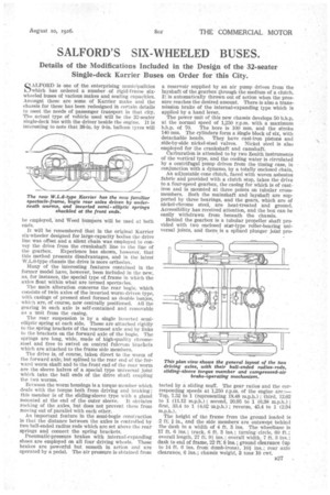
The main alteration concerns the rear bogie, which consists of twin axles of the inverted worm-driven type, with casings of pressed steel formed as double banjos, which are, of course, ndw centrally positioned. All the gearing in each axle is self-contained and removable as a unit from the casing. The rear suspension is by a single Inverted semielliptic spring at each side. These are attached rigidly to the Spring brackets of the rearmost axle and by links to the brackets on the forward axle of the bogie. The springs are long, wide, made of high-quality chromesteel and free to swivel on central fulcrum brackets which are attached to the frame side members.
The drive is, of course, taken direct to the worm of the forward axle; but splined to the rear end of the forward worm shaft and to.the front end of the rear worm are the sleeve halves of a special type universal joint which take the ball ends of the drive shaft coupling the two worms.
Between the Worm housings is a torque member which deals with the torque both from driving and braking; this member is of the sliding-sleeve type with a gland mounted at the end of the outer sleeve. It obviates rocking of the axles, but does not prevent them from moving out of parallel with each other.
An important feature in the semi-bogie construction is that the distance between the axles is controlled by two ball-ended radius rods which are set above the rear springs and connect the spring brackets.
PneumatiC-pressure brakes with internal-expanding shoes are employed on all four driving wheels, These brakes are powerful but, smooth in action and are operated by a pedal. The air pressure is obtained from a reservoir supplied by an air pump driven from the layshaft of the gearbox through the medium of a clutch. It is automatically thrown out of action when the pressure reaches the desired amount. There is also a transmission brake of the internal-expanding type which is applied by a hand lever.
The power unit of this new chassis develops 50 b.h.p. at the normal speed of 1,250 r.p.m. with a maximum b.h.p. of 70. The bore is 100 mm. and the stroke 140 mm. The cylinders form a angle block of six, with detachable heads. They have cast-iron pistons and side-by-side nickel-steel valves. Nickel steel is also employed for the crankshaft and camshaft.
Carburation is attended to by two Zenith instruments of the vertical type, and the cooling water is circulated by a centrifugal pump driven frotn the timing case, in conjunction with a dynamo, by a totally enclosed chain.
An adjustable cone clutch, faced with woven asbestos fabric and provided with a clutch stop, takes the drive to a four-speed gearbox, the casing for which is of castiron and is mounted at three points on tubular crossmembers. Both the mainshaft and layshaft are supported by three bearings, and the gears, which are of nickel-chrome steel, are heat-treated and ground. Accessibility has received attention, and the box can be easily withdrawn from beneath the chassis.
Behind the gearbox is a tubular propeller shaft provided with two enclosed star-type roller-bearing universal joints, and there is a splined plunger joint pro.
tected by a sliding muff. The gear ratios and the corresponding speeds at 1,250 r.p.m. of the engine are :Top, 7.52 to 1 (representing 18.48 m.p.h.); third, 12.02 to 1 (11.12 m.p.h.); second, 20.95 to 1 (6.38 m.p.h.); first, 33.4 to 1 (4.02 'm.p.h.) ; reverse, 45.4 to 1 (2.04 m.p.h.).
The height of the frame from the ground loaded is 2 ft: in., and the side members are outswept behind the dash to a width of 4 ft. 3 ins. The wheelbase is 17 ft. 6 ins.; track, 6 ft. 3 ins.; turning circle, 60 ft.; overall length, 27 ft 91 ins.; overall width. 7 ft. 3 ins.; dash to end of frame, 22 ft: 8 ins.; • ground clearance (up to 14 ft. 6 ins, from dumb-irons), 10* ins.; rear axle clearance, 6 ins.; chassis weight, 3 tons 10 cwt.