


Patents Completed.
Page 22
If you've noticed an error in this article please click here to report it so we can fix it.
Westinghouse Electric Starter. Wheel Bearings. A Manual Starter. Contact Breaker Mechanism.
Copies of complete specifications of the patents published on this page can be obtained from the Sales Branch, Patent Office, Holborn, W.C., at the cost of sixpence for each specification.
THE BRITISH WESTINGHOUSE \ELECTRICAL MANUFACTURING CO., LTD., No. 100,006, dated under International Convention 5th January, 1915.—In electric staiters in which, the armature is maved. longitudinally to eie;age its Pinion with the flywheel, it is desirable to obtain this longitudinal movemenz before the armature is set in rotation. This result is obtained according to the .present invention by so arranging the field-winding of thejnotor that the armature is electrically held from rotation clueing the first switching position.
In a. four-pole motor, the field-winding and its switching gear is so arranged that on the first position two opposite poles are caused to have different polarity instead of the same polarity. The machine is therefore virtually a twopole machine, but since the armature is wound for four poles it will either not move or move only slowly in one direction. This slow movement may be ensured by making one pole. winding slightly stronger than the other.
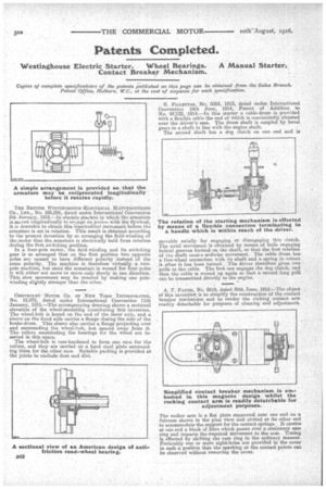
CEEVROLET MOTOR CO. OF NEW YORK INCORPORATED, No. 12,972, dated under International Convention 11th January, 1915.—The accompanying drawing shows a sectional elevation of the wheel-mounting constituting this invention. The wheel-hub is keyed on the end, of the inner axle, and a sleeve on the fixed axle carries a flange closing the side of the brake-drum. This sleeve also carries a flange projecting over and surrounding the wheel-hub, but spaced away from it. The rollers constituting the bearings for the wheel are inserted in this space.
The wheel-hub is case-hardened to form one race for the rollers, and they are carried on a hard steel plate surrounding them for the other race. Suitable packing is provided at the joints to exclude dust and dirt. E. FILLETTAZ, No. 8365, 1915, dated under International Convention lath June, 1914, Patent of Addition to No. 24122, 1914.—In this starter a cable-drum is provided with a flexible cable the end of which is conveniently situated near the driver's seat. The drum shaft is coupled by bevel gears to a shaft in line with the engine shaft. The second shaft has a dog clutch on one end and is
movable axially for engaging or disengaging this clutch. The axial movement is obtained by means of balls engaging helical grooves formed on the shaft, so that the first rotation of the shaft causes endwise movement. The cable drum has a free-wheel connection with its shaft and a spring to return it after it has been turned. The driver therefore gives two pulls to the cable. The first one engages the dog clutch, and then the cable is wound up again so that a second long pull can be transmitted directly to the engine.
A. F. PAYNE, No. 9519, dated 30th June, 1915.—The object of this invention is to simplify the construction of the contact breaker mechanism and to render the rocking contact arm readily detachable for purposes of cleaning and adjustment.
The rocker arm is a flat plate supported near one end on a fulcrum shown in the plan view and slotted at its other end to accommodate the support for the contact springs. It carries at one end a block of fibre which passes over a stationary earn ring and imparts the i.equired movement to the arm. Timing is effected by shifting the cam ring in the ordinary manner. Preferably one or more sight-holes are provided in the cover in such a position that the sparking at the contact points can be observed without removing the cover.