


A Compact Gearbox
Page 56
If you've noticed an error in this article please click here to report it so we can fix it.
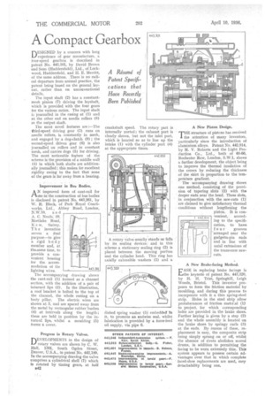
DESIGNED by a concern with long experience of gear manufacture, a four-speed gearbox is described in patent No. 443,301, by David Brown and Sons (Huddersfield), Ltd., of Lock-wood, Huddersfield, and H. E. Merritt, of the same address. There is no radical departure from normal practice, the patent being based on the general layout, rather than on unconventional details.
The input shaft (2) has a constantmesh pinion (7) driving the layshaft, which is provided with the four gears for the various ratios. The input shaft is journalled in the casing at (1) and at the other end on needle rollers (8) in the output shaft.
The most novel features are ;—The third-speed driving gear (3) runs on needle rollers, is constantly in mesh, and engaged by a dog-clutch (9) ; the second-speed driven gear (6) is also journalled on rollers and in constant mesh, and carries dogs (5) for driving. The most noticeable feature of the scheme is the provision of a middle wall (4) in which both shafts are additionally journalled; this makes for excellent rigidity owing to the fact that none of the gears is far away from a bearing.
Improvement in Bus Bodies.
AN improvedform of cant-rail for trse in the construction of bus bodies is disclosed in patent No. 443,261, by W. R. Black, of Park Royal Coachworks, Ltd:, Abbey Road, London, N.A.17.10. and A. C. Needs; sp, Mortlake. Road, K e 4V, Surrey. Tb e-invention serves a dual purpose—to .give a rigid body member and, at the.same time, to provide a convenient housing for the. accommodation of the lighting wires.
The accompanying drawing shows the cant-rail (1) formed as a channel section, with the addition of a pair of inturned lips (2). In the illustration, a roof bracket is bolted to the top of the channel, the whole resting on a body pillar. The electric wires are shown at 3, and are spaced away from the metal by rectangular rubber'bushes (4) at intervals along the length ; these are held in position by the inflamed lips, whilst a moulding (5) forms a cover.
Progress in Rotary Valves.
DEVELOPMENTS in the design of rotary valves are shown by C. W. Hall, 1301, South Ogden Street, Denver, U.S.A., in patent No, 442,189. In the accompanying drawing the valve comprises a cylindrical shell (7) which is rotated by timing gears, at half
n42 crankshaft speed. The rotary part is internally ported ; the exhaust port is clearly shown, but not the inlet part, which is located so as to line up the intake (1) with the cylinder port (4) at the appropriate times.
A rotary valve, usually stands or fa la by its sealing devices: and in this scheme a stationary sealing ring (2) is placed between the moving portion and the cylinder head. This ring has axially extensible washers (3) and a
dished spring washer (* embedded-1'n it, to promote an endwise seal, whilst lubrication is provided by a force-feed oil supply, via pipe 6.
A New Piston Design.
THE structure of pistons has received the attention of many inventors, particularly since the introduction of aluminium alloys. Patent No. 442,914, by M. V. Roberts and the Light Production Co., Ltd., both of 60-66, Rochester. Row, London, S.W:1, shows a further development, the object being to improve the thermal insulation of the crown by reducing the thickness of the skirt in proportion to the temperature gradient.
The accompanying drawing shows one method, consisting of the provision of tapering slots (2) with the deeper ends near the head. These slots, in . conjunction with the saw-cuts (1)' are claimed to give 'satisfactory thermal conditions without lengthening .the piston. It is convenient, according to the specification, to have
f our grooves -arranged near the gudgeOn-pin ends and in line with axial extensions of the transverse sawcuts.
' A New Brake-facing Method.
EASE in replacing brake facings is the keynote of patent No. 443,320, by H. H. Trist, Springhill, Leigh Woods, Bristol. This inventor proposes to form the friction material by moulding, and during this process to incorporate with it a thin spring-steel strip. Holes in the steel strip allow protuberances of friction material (1) to project, for which corresponding holes are provided in the brake shoes. Further keying is given by a step (2) and the whole assembly is located on the brake shoes by springy curls (3) at the ends. By reason of these, replacement is easy, the composite strip being simply sprung on or off, whilst the absence of rivets abolishes scored drums, in addition to permitting the facing to be worn extremely thin. This system appears to possess certain advantages over that in which complete faced-shoe replacements are used, easy detachability being one.