


HOW OVERTYPE STEAM I
Page 18
Page 19
Page 20
Page 21
If you've noticed an error in this article please click here to report it so we can fix it.
4S COULD BE IMPROVED.
An Analysis of the Present Designs of th which Incorporates Improvement Up
Steam Wagon and a Suggested Design ters which Now Call for Criticism.
FROM TIME to time various arguments have been raised as to the relative merits of the overtype design of steam wagon, as compared with the undertype design. This question has again been brought to the fore by the fact that various makers of overtype -wagons have produced, or are producing, undertype models. Seine makers claira that both types have their respective .me l its, and uses; they recommend the overtype as a universal machine, and the undertype'loi long distance work on first-class roads.
The object of this article is not a comparison of these two types, but an analye• of the present designs 'of •the evertype, together with suggestions for its improvement. It is not intended to advocate the overtype as the best design of steam wagon ;, this point, has previously been .discussed by the writer in The Commercial Motor, but, in view of the great popularity of this types especially amongst drivers, perhaps a useful purpose can be served by criticising present designs and offering suggestions for possible improvements.
When. steam wagons were first produced under the present laws, they were all of the undertype design, the overtype being introduced by Fodens, Ltd., during the War Office trials at Liverpool in 1901. Subsequently, the majority of undertypes were abandoned, and the Foden was copied' by many other makers with but little variation. Since its introduction, very little development in design has taken place, and it is rather surprising that many makers should now show a tendency to abandon it without first making an attempt, on original lines, to overcome such defects as' may be discovered in it.
General Description of the Overtype.
The overtype design is really a combined traction engine and trailer wagon, the following being its
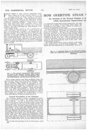
main features. It has a _locomotive boiler fixed between the chassis frame members, with a compound engine mounted on the top of the boiler barrel, the crankshaft main bearings being carried by upward extensions of the firebox shell-plates, usually called horn-plates. It has. spur-gear drive from the crankshaft to the intermediate shaft, which is carried on one side between the boiler and the frame .member, consisting of two speeds with change gear. There is single roller chain drive from the intermediate shaft to the back axle. The differential is situated on the back axle, except in the case of the Burrell steamer, which has this gear fitted on the intermediate shaft and has double chain drive to each -wheel on the back axle.
Front axle and steering of the traction-engine type e32 are employed, giving three-point suspension, the axle turning on a centre fore-carriage fixed below the smokebox of the bailer. Fig. 1 shows in outline the general arrangement of this type. In the majority of designs there is a space of about 2 ft. 6 ins, between the boiler and the body, which forms the footplate. There is one exception to this, however, and that is the Mann steam wagon,, where the body is close up to the boiler and the driver efts alongside the firebox, the fire-door being at the side instead of at the rear end. This arrangement gives a shorter wheelbase, and also a good position for the driver so far as regards his view of the road. This is illustrated in Fig. 3.
• One of, the chief merits of the overtype is its popularity with drivers, as previously mentioned. The reason for this popularity is, undoubtedly, because of
the similarity to its old-established predecessors —the railway locomotive and the traction engine. Its accessibility, especially of the engine, is far superior to that of any other type so far in use. Such operations as adjusting crankshaft bearings, connectingrod bearings, and eccentric straps, can easily be carried out without interfering with any other part. Half an hour with a spanner on this type of engine will often remedy a "knock" when a similar defect on the undertype might take much longer, chiefly spent in dismounting and refitting parts other than those which require adjustment. It is simple in design, and all the parts are of a familiar type; therefore it , is easily understood by drivers and mechanics. Take, for instance, the backaxle gear of present-type steam wagons ; this is one of the simplest and most reliable of components. When fittePwith machine-cut enclosed differential gear, made from steel stampings, as are now chiefly used, it is practically indestructible. These axles will run for years with no further attention than keeping the oil-boxes full of . oil, and.an occasional rebedding of the bearing brasses.
The loco.-type boiler canot be said to be the simplest type, but it is a very familiar one, and, although it is liable at times to give tube trouble, this can quickly be remedied. Repairs can also easily be carried out. The stoking is very simple and efficient, the condition of the fire being observed by the driver witheat any difficulty.
From the heat economy point of view, the overtype arrangement of compound cylinders mounted directly on the top of the boiler barrel is very hard to beat, and the fuel consumption is very good.
Weak Points in Design.
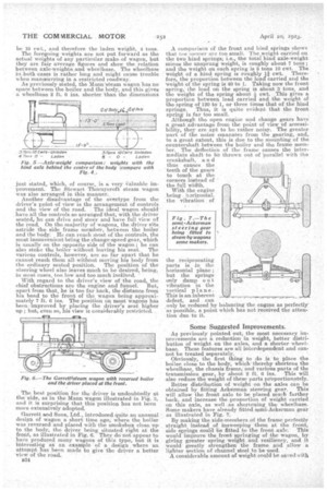
Turning now to the weak points in the overtype,' the chief objections are its heaviness, weight distribution and long wheelbase. In order to keep the back ax-weight within practicable limits, it is necessary tie ‘; the axle should be placed behind the centre of the body. If it be placed directly under the centre, it will have to bear the full weight of the load carried; but, by placing it behind the centre of the body, part of the load weight will be thrown on the front axle.
To illustrate this, take a five-ton wagon with a body 13 ft. long. If the hind axle be placed under the centre of the body, the wheelbase will be approximately 14 ft. 3 ins., as shown in Fig. 4. The unladen weight of the wagon in working order will be about '7 tons, and the approximitte axle-weights : front, 3 tons 5 *cwt. ; hind, 3 tons 15 cwt. If a net load of 5 tons be placed on the wagon, the front axle-weight will remain the same, and the hind axle-weight will become 8 tons 15 cwt. ; the total weight being 12 tons. If now the hind axle be placed 1 ft. 6 ins, behind the centre of the body, as shown in Fig. 5. the wheelbase will be 15 ft. 9 ins., and the weight distribution will be as follows : The unladen axle-weights of the vehicle in working order will be a little different fropa those in the previous case, as more weight will be on the front axle, which will then be increased to approximately 3 tons 10 owt.' and the hind axle-weight reduced to 3 tons 10 cwt. With a net load of 5 tons, the proportion of this weight on the hind axle would be 5 X 141 ÷ 151 = 4.52 tons, say, 4 tons 10 cwt. ; and the laden hind axle-weight will be 8 tons. The proportion of the load weight on the front axle will
be 10 cwt., and therefore the laden weight, 4 tons.
The foregoing weights are riot put forward as the actual weights of any particular make ofwagon, but they are fair average figures and show the relation between axle-weights.and wheelbase. The wheelbase in, both Cases is rather long and might cause trouble when manoeuvring in a restricted roadway. As previously stated, the Mann' steam wagon has no space between the boiler and the body, and this gives a wheelbase 2 ft. 6 ins, shorter than the dimensions just stated, which, of course, is a very l'aluable improvement. The Stewart Thernyeroft steam wagon was also arranged in this manner.
Another disadvantage of the overtype from the driver's point of view is the arrangement of controls and the view of the road. The ideal wagon should' have all the controls so arranged that, with the driVer seated he can drive and steer and have full view of the 'road, On the majority of wagons, the driver sits astride the side frame in-ember, between the boiler and the body. He can reach most of the controls, the most inconvenient being the change-speed-gear, which is usually on the opposite side of the wagon; he can also stoke the boiler without leaving his seat. The various controls, however, are so far apart that he cannot reach them all without moving his body from the ordinary seated position. The position of the steering wheel also leaves much to he desired, being, in most eases, too. low and too much inclined.
With regard to the driver's view of the road, the chief obstructions are the engine and funnel. But, apart from that, he is too far back, the distance from his head to the front of the wagon being approximately 7 ft. 6 ins. The position on most wagons has been.-improved by placing the driver's seat higher up ; but, even so, his view is considerably restricted.
The hest position for the driver is undoubtedly at the 'side, as in the Mann wagon illustrated-in Fig. 3, and it is surprising that this position has not been more extensively adopted.
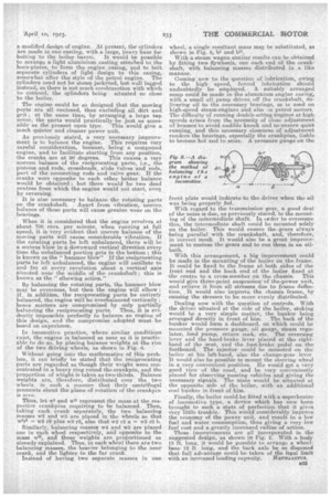
Garrett and Sons, Ltd., introduced quite an unusual design of wagon a short time ago; where the boiler was reversed and placed with the smokebox close up to the body, the driver being sittiated right at the front, as illustrated in Fig, O. They do hot appear to have Produced many Wagons of this type, but it is interesting asan exaMple of a deign where an attempt has been made to give the: driver a better view of the road.
B31
A comparison of the front and hind springs shows that tile Tormer arc too small. The ,weight carried on the two hind springs; he:, the fetal hind axle-weight minus the unsprung weight, is roughly about 7 tone; and the weight on each spring is 3 tons 10 cwt. The weight of a hind spring is roughly 1i -cwt. Therefore, the proportion between the load carried and the weight of the spring is 40 to 1. Taking now the front spring, the load on the spring is about 3 tons, and the weight of the spring about cwt. This gives a proportion between load carried and the weight of the spring of 120 to 1, or three times that of the hind springs. Thus, it is quite evident that the front spring is far too small. Although the open engine -and change gears have a Feat 'advantage from the point of view ofaccessibility, they are apt to be rather noisy. The greater part of the noise emanates from the gearing, and, to a great extent, this is due to the mounting of the countershaft between the boiler and the frame member. The deflection of the frame causes the intermediate shaft to be thrown out of Parallel with the
crankshaft, a n d thus causes the teeth of the gears to touch at the corners instead of the full width.
With the engine being horizontal, the vibration of the reciprocating parts is in the horizontal plane; but the springs only damp out vibration in the vertical pl ane. This is an inherent defect, and can only be reduced by balancing the engine as perfectly as possible, a point Which has not received the attention due to it.
Some Suggested Improvements.
As previously pointed out, the most necessary improvements are a reduetion in weight, better distribution of weight on the axles, and a shorter wheelbase. These features. are all interdependent and cannot be treated separately.
Obviously, the first thing to do is to place the boiler, close to the body, which thereby shortens the wheelbase, the chassis frame, and various parts of the transmission gear, by about 2 ft: 6 ins. This will also reduce the weight of these parts proportionately.
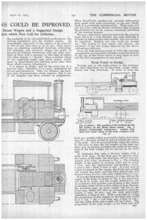
Better distribution of weight on the axles can be obtained by fitting Ackerman steering gear. This will allow the front axle to be placed much farther back, and increase the proportion of weight carried on this axle, as well as shortening the wheelbase. Some makers have already fitted semi-Ackerman-gear as illustrated in Fig.. 7.
By making the side-members ,of the frame perfectly straight instead of insweeping them at the front, side springs could be fitted to the front axle. This would improve the front springing of the wagon, by giving greater spring weight and resiliency, and it would greatly strengthen the frame and allow a lighter section of channel steel to be used. A considerable amount a weight could be saved with
a modified design of engine. At present, the cylinders are made in one casting, with a large, heavy base for bolting to the boiler barrel. It would be possible to arrange a light aluminium casting attached to the horn-plates, to form the engine easing, and to bolt separate cylinders of light design to this easing, somewhat after the style of the petrol engine. The cylinders need not be steam jacketed, but well lagged instead, as there is not much condensation with which to contend, the oylinders being situated so close to the boiler.
The engine could be so designed that the moving parts are all enclosed, thus excluding all dirt and grit ; at the same time, by arranging a large top cover, the parts would practically be just as accessible as the present open type. This would give a much quieter and cleaner power unit.
As previously stated, a very necessary improvement is to balance the engine. This requires very careful consideration, because, being a compound engine, and to facilitate starting from any position, the cranks are at 90 degrees. This causes a very uneven, balance of the reciprocating parts, i.e., the pistons and rods, crossheads, slide valves and rods, part of the connecting reds and valve gear: If the cranks were opposite to each other better balance would be obtained ; but there would be two dead centres from which the engine would not start, eveit by reversing.
It is also necessary to balance the rotating parts on the crankshaft. Apart from vibration, uneven balance of these parts will cause greater wear on the bearings.
When it is considered that the engine revolves at about 700 revs, per minute when running at full speed, it is very evident that uneven balance of the moving parts will cause considerable vibration. If the rotating parts be left unbalanced, there will be a serious blow in a downward vertical direction every time the unbalanced portion gets to the-bottom; this is known as the "hammer blow" If the reciprocating parts be left unbalanced, the engine will oscillate to and fro at every revolution about a vertical axis situated near the middle of the crankshaft ; this is known as the "elbowing action."
By balancing the rotating parts., the hammer blow may be overcome, but then the engine will elbow ; if, in addition, the reciprocating parts be entirely balanced, the engine will be overbalanced vertically ; hence matters are compromised by only partially balancing the reciprocating parts. Thus, it is evidently impossible perfectly to balance an engine of this design, and the compromise adopted must be based on experience.
In locomotive practice, where similar conditions exist, the engine is balanced as near as it is practicable ta do so, by placing balance weights at the rim of the two driving wheels, as shown in Fig. S.
Without going into the mathematics of this problem, it can briefly be stated that the reciprocating parts are regarded as though their weight were concentrated in a. heavy ring round the crankpin and the proportion of wWglit is taken as two-thirds. Balance weights are, therefore, distributed over the two wheels, in sueli a manner that their centrifugal moments about the plane of rotation of the crankpin is zero.
Thus, let wi and TOrepresent the mass at the respective erankpies requiring to be balanced. Then, taking each crank separately, the two balancing masses w`2 and w3 are placed in the wheels so that -wha = w2 r2 plus w3 rO, also that w2 r2 a = w3 r3 b.
Similarly, balancing masses we and w5 are placed one in each wheel respectively, and opposite to the Maas Wit, and these weights are proportioned as already explained. Thus, in each wheel there are two balancing masses, the heavier belonging to the near crank, and the lighter to the far crank.
Instead of having two separate masses in one wheel, a single resultant mass may be substituted, as shown in Fig. 8, bt and bll. With a steam wagon similar results can he obtained by fitting two flywheels, one each end of the crankshaft, with balancing masses distributed in a like manner.
Coming now to the question of lubrication, owing to the high speed, forced lubrication should undoubtedly be employed. A suitably arranged sump could be made in the aluminium engine casing, with a small oil pump driven off the crankshaft, delivering oil to the necessary bearings, as is used on high-speed steam-engines and also in petrol motors. The difficulty of running double-acting engines at high speeds arises from the necessity of close adjustment of brasses to avoid audible knock and to ensure quiet running, and this necessary closeness of adjustment renders the bearings, especially the crankpins, liable to become hot and to seize. A pressure gauge on the front plate would indic.atie to the driver when the oil was being properly fed. With regard to the transmission gear, a good deal of the noise is due, as previously stated, 'to the mounting of the intermediate shaft. In ceder to Overcome this, the intermediate shaft could be mounted solely on the boiler. This would ensure the-gears always being parallel with the crankshaft, and, therefore, in -correct mesh. It would also be a great improvement to enclose the gears and to run them in an oilbath.
With this arrangement, a big improvement could be made in the mounting of the boiler on the frame. It could be fixed to the frame at both sides of the front end and the back end of the boiler fixed at -the centre to a cross-member ,en the chassis. This wouid give, three-point suspension' of the-power unit, and relieve it from all stresses due to frame deflection. , It would also improve the chassis frame, by causing the skesses to be more evenly distributed.
Dealing now with the question of controls. With the driver situated at the side of the boiler, stoking would be a very simple matter, the bunker being arranged directly in front of him. The back of the bunker would form a dashboard, on which could be mounted the pressure gauge, oil gauge, steam regulator, feed pump, return cock, etc. The reversing lever and the hand-brake lever placed at the righthand of the seat, and the foot-brake pedal on the footboard. The injector could be mounted on the boiler at. his left-hand, also the change-gear, lever It would also be possible to mount the steering wheel in a very convenient position. He would get a very good view of the road, and be very conveniently placed for observing passing vehicies and giving the necessary signals. The mate would be situated at the opposite side of the bailer, with an additional coal bunker in -front of him.
Finally, the boiler could be fitted with a superheater of locomotive type, a device which has now been brought to such a state of perfection that it gives Very little. trouble.. This wOuld considerably improve the economy of the power unit, and, result in a low fuel and water consumption, thus giving a very law fuel cost-and a greatly increased radius of action.
These improvements are all incorporated in the suggested design, -as shown in Fig. 2. With a body 13 ft. long, it would be possible to arrange a wheelbase 12 ft. long, and the back axle be se disposed that full advantage could be taken a the legal limit
with an increased loading capacity. HEPHAEuus.