


A WHEEL WHICH ABSORBS SHOCKS.
Page 12
Page 13
If you've noticed an error in this article please click here to report it so we can fix it.
A Test of the L.H.B. Spring Wheel, in Which Road Shocks. Are Taken Up Between Tyre and Hub.
WE RECENTLY had an opportunity of testing on the road the effect of the L.H.B. spring wheel in the reduction of vehicle vibration. It must be understeed that this wheel is not intended to replace the usual springs of a lorry. Its object is to provide a certain amount of yield which will reduce the harshness of the blows of the tyres on a rough road. It is found that a very small amount of yield between the rim of a 'wheel and its axle has a. very beneficial effect on all parts of a vehicle'.
The lorry on which we tested the device was an ordinary Ii-ton lorry
vehicle, fitted.with springs of the usual leaf construction fully up to ordinary strength. We mention this fact because, in many instances, where we have been asked to try spring wheels, resilient
tyres, shock-absorbing hubs, and similar devices, we have found the vehicle on which the trial was to be made was fitted with springs of extraordinary length and suppleness. Before commencing the trial we made sure that the leaf springs were of normal proportions for the load. We also took the precaution to make sure that the tyres were of normal size, and had no special features about them which would reduce vibration.
The vehicle in question was fitted with wheels to both back and front axles. This enabled us to make sure that the special wheels did not in any way
interfere with the steering. Fortunately the day was wet, which gave us an opportunity of testing the tyres under conditions likely to bring about a sideslip. The vehicle was loaded to its full capacity of 1i tons. The load consisted of various pieces of machine castings, among which were small spindles, which were lying on the floor of the body loosely. With ordinary springs one would expect such articles to rattle and jump about when rough roads were being traversed. We noticed, however, that they did not do so.
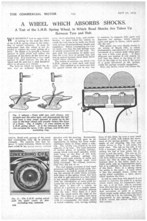
The road chosen consisted of bad wood pavement and badly pot-holed roads. Unfortunately, we had-no means of measuring the amount of yield which actually took place in the spring wheel, but here we wish to call attention to a fact which is not usually understood in connection with the introduction of some yield betv:een the rim of the wheel and the axle. The point is this :—If a vehicle he driven at a pot-hole at a certain speed, there is a drop when actually passing over the hole. Then there is a blow when the wheel meets the edge of the hole. This blew is so sudden and sharp that the ordinary springs cannot deal with it; consequently, the whole vehicle is raised suddenly, and, having nothing to continue its support, falls again and depresses the springs, which rebound again and again in waves, which gradually die out. This action was very clearly shown in our article of March 13th, in which photographic reproductions of the actual movement of a vehiale body when pass ing over a hole were given. If these diagrams are studied it will clearly be seen that the effect of the blow of the tyre on the edge of the hole is the cause of a great movement in the springs, which the springs actually exaggerate. Now, any device which will reduce the force of this blow, by even a very small amount of yield, will reduce the movement of the springs greatly. As an example of our meaning, the two cold chisels shown in Fig. I will make the point clear. The one on the left, if hit with a hammer„ will have the effect of cutting the bar of iron which lies between it and the anvil. The one on the right, although hit with the same force; will have little or no cutting effect. The reason for this is that, although the hammer blow is the same, there is a slight yield, only an imperceptible yield, but it is sufficient to destroy the effect of the blow. Now, in a spring wheel the action is the same.A rigid wheel is like the straight chisel, whilst the spring wheel resembles a bent chisel, which deadens the blow.
It will be seen•from this thateit is not correct to measure the yield in a spring wheel, which may, for argument's sake, be, say. If of an inch, and to conclude from this that the movement of the body is reduced by that amount. An of an inch movement or yield in a spring wheel might easily reduce the movement of the body by 1 in. by reducing the blow transmitted to the springs. Thatthe L.R.B. wheels did reduce vibration we feel certain.
The next matter about which we wanted to assure. ourselves was durability. We have no facts other than 'a ceriificate from the R.A.C., which says
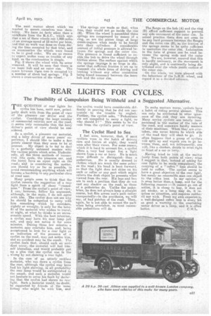
• that a set of these wheels ran 1,000 miles ;:t an average speed of 18 miles per hour, and that no wbrk was dens on them dm-' ing the time occupied by that trial, and on examination the wheels were found to be in goad order. We see no reason toexpect undue wear or.. trouble of any kind, as the construction is simple. Fig. 2 shows the wheel with Its cover removed. It will be seen that there is an inner hub and an outer rim. The space between these two is occupied by a number of short leaf springs. Fig. 3 shows a cross-section of the wheel. The springs are made so that-, -when free, they would not go inside the rim (B). When the wheel is assembled these springs are compressed by means of a ring, as are the piston rings of large steam-engines when ready to be forced into their cylinders. A considerabla amount of initial pressure is allowed between the springs and the outer rim. This pressure is found sufficient to enable the hub to drive the wheel through friction alone. The surface against which the springs impinge is so large in diameter that sufficient friction is set up to transmit the whole force of driving and braking 'without any other connection being found necessary between the inner hub and the outer rim.. The flange on the hub (A) and the ring (D) afford sufficient support, to prevent any side movement of the outer rim. In actual practice there does not seem to be any hard pressure het-wen the flanges and the enter. rim (13), as the friction of the springsseems to be quite sufficient to centralize the outer rim. Lubrication in the form of grease can' be used between the spring ends and the outer rim. We area however, assured that this is hardly necessary, as the movement is only slight, and is continually being dis• tribute ii over the whole inside surface of the outer rim.
On the whole, we were pleased with the behaviour of the L.H.B.wheel, and regard it as a decided advance.