


SIMPLIFYING TRANSMISSION AND CONTROL.
Page 27
Page 28
If you've noticed an error in this article please click here to report it so we can fix it.
A New and Practical Mechanism to Replace the Gearbox. Infinite Range of Automatically Adjusted Speed Ratios.
SO, MANY unsuccessful attempts have been made to replace the orthodox threeor four-speed gearbox by a mechanism which should provide an infinite range of speed ratios, that the public has naturally become somewhat sceptical of the merits, of.." infinitely variable gears." _Electric transmission asemployed in all petrol-electric vehicles is the only outstanding example of success attained in this direetiOn. A. little consideration given to this success arid to the immense advantages possessed by a workable
gear of the infinitely variable type will show that it can only be a question of time before the step-ratio gearbox is superseded. A truly automatic, infinitely variable transmission would relieve the driver of troublesome gear-chang ing, would obviate the need for a clutch, would sim plify the chassis, and would lessen the wear and tear on the vehicle. These are obvious points, but, in addition, higher average speeds and better consump tion figures could be obtained, owing to the fact that the engine would be provided with the correct gear
ratio under each and every condition of roads and loading. For this reason it would probably. be possible to reduce the size and power of the engine.
The transmission we have now to deactribe is 31a,inaed to have all these advantages. Furthermore, it at once commands attention by the simplicity and cleverness of the mechanism, and the novel principle of operation whieh obviates the use of gearing. That it will do all that is claimed for it has been proved by exhaustive tests on the bench and on the road.
The inventor is Mr. G. Constantinesco, well known as an engineer, scientist, and mathematician, and author of a standard work on sorties (wave transmission). Mr. Constantinesco was responsible for the famous C.C.. gun synchronization gear—used on praetically every military aeroplane in the latter part of the war—which enabled a machine-gun to fire at the rate of . 10 shots a second through a propeller whirling at anything up to 2,000 r.p.m. •without touching the blades.
In view of his work on hydraulics and wave motions, one would have anticipated that Mr. Constantinesco would have designed a fluid transmission, hut this is not the cam; the gear • is purely mechanical. It was .first described in an
instructive article in last week's iSsue of The Motor.
Here let us drop the word " gear," which does not in any way express the functioning of this mechanism. "Torque converter " is the name given to it by the inventor, and this is the best term that can be used. By "torque " is meant the twisting effect produced on a shaft or other part. Unlike the steam-engine, a petrol power unit does not develop a high torque at low speeds ; indeed, the torque delivered is much the same from 300 r.p.m. to 4000 r.p.m. Canso quently when starting, or when ascending a gradient, this torque must be converted to a much higher value, with a concurrent decrease in the speed of the vehicle.
In the Constantinesco converter the amount by which the torque is amplified is automatically pontrolled by the resistance to motion so that the speed of the vehicle is maintained at the highest Possible value consistent with the running conditions and the power delivered by the engine.
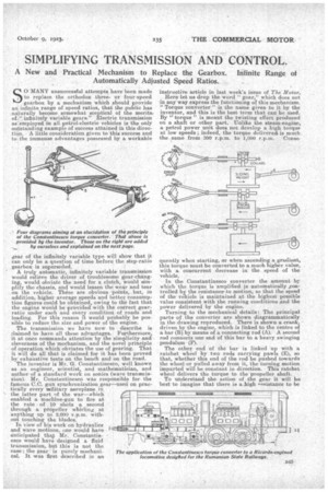
Turning to the mechanical details: The principal parts of, the converter are shown diagrammatically in the drawing reproduced. There is shown a crank, driven by the engine, which is linked to the centre of a bar (B). by means of a connecting rod (A). A second rod connects one end of this bar to a•heavy swinging pendulum (F).
The other end of the bar is linked up with a ratchet wheel by two rods carrying •pawls (E), so that, whether this end of the rod be pushed towards the wheel or pulled away from it, the turning motion imparted will be constant in direction. This ratchet wheel delivers the torque to the propeller shaft.
To understand the action of the gear it will be best to imagine that there is a _high nsistance to be overcome ; thus, suppose the vehicle is to be started on an upward gradient, all that the driver has to do is to start the engine and then depress the accelerator pedal while releasing the hand brake. Let us see how the converter will pick up the load: When the engine is driving the crank at a low speed it will impart an oscillating motion to the pendulum without moving the ratchet wheel. As the throttle is opened, the tendency would be for the pendulum to be forced to swing faster and faster. This motion is resisted, however, by the swinging mass, which imposes a heavier and heavier load on the pawls as the engine speeds up. Finally, this load suffices to move the ratchet wheel; and the vehicle gradually gathers speed.
It will be obvious that, when the resistance is sufficiently small, the converter will transmit the torque
without any movement ef the pendulum. Between this condition and the opposite extreme (a very high resistance), the oscillations of the pendulum and the degree by which the torque is amplified will vary in accordance with the load.
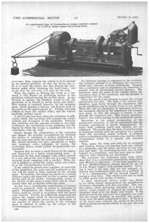
Simple though the conetruction of the converter may appear, the peculiar arrangement for utilizing the inertia or resistance to motion produced by a moving mass may make the principle rather obscure. The second drawing has been reproduced to make this principle clear, although, of course, the mechanism shown would neither be practicable nor automatic.
Suppose that we have a crank driven by the engine and connected to a heavy reciprocating mass. A projection on this mass engages with collars secured to a rod, and at the end of this rod is a pair of rods carrying pawls engaging with a ratchet. When the rod is pushed or pulled the rachet wheel will rotate, as in the Constantinesco converter.
If the collars be placed close together, at each `side of the projection, the push and pull produced on the rod will be equal to those imposed on the moving mass. If, however, the collars be placed at a certain distance apart, the mass will be free to gather speed during part of its stroke. Consequently, owing to the inertia of the mass, a ,large force will be transmitted when the projection meets the collar.
In this way a considerable• amplification of torque could be produced, with, of course, a reduction of
speed. Furthermore, the distance separating the collars could be varied in accordance with the speed ratio desired. Finally, by sufficiently separating the collars the engine could be disconnected entirely. This simple conception serves as an illustration of the manner in which the inertia of the swinging mass is utilized to• build up the torque in the Con stantinesco converter.
B46 An electrical analogy is suggested by the inventor, who actually utilized it in designing the tonverter, which may interest wireless enthusiasts. Suppose that a resistance and an impedance are connected in parallel with an alternating current dynamo. The resistance takes the place of the ratchet wheel, the impedance that of the pendulum, and the dynamo is substituted for the crank.
When the speed of the dynamo is small, the current alternations are slow. The bulk of the current will, therefore, pass freely through the impedance, just as the pendulum can be swung freely at low speeds. When the rate of alternation is increased, however, the resistance offered by the impedance coil becomes very great, so that the current is forced to flow through the resistance coil. This circuit, therefore, forms a very useful analogy to the mechanical system.
Reverting to the actual construction of the mechanical converter, it will be understood that the drawing reproduced is purely diagrammatic. To begin with, ordinary pawls and ratchets are not employed. The pawls take the form of pivoted pads, in frictional contact with the periphery of a smooth wheel (the free-wheel clutch method). A wedging action is produced which prevents slip, and the whole arrangement works in a smooth and noiseless manner.
Then, again, the arms and rods are so arranged that bending strains and bearing loads are reduced to a minimum, and the whole converter is very compact and light. An oscillating flywheel can be used instead of a pendulum, and this part may be duplicated so that vibrations are diminished.
The converter has undergone many tests which show that it is a practicable proposition, being silent and efficient in operation. It has been applied to a 40 h.p. Sheffield-Simplex chassis, driven by an old 10 h.p. Singer engine, with marked success. Carrying a load of ten men, this car was stopped, restarted and accelerated with ease on a gradient of 1 in 8; subsequently, tierear proved capable of towing a 4-ton lorry. The vehicle could also be made to climb slowly over baulks of timber. • A small electrically driven model was shown to us which clearly demonstrated the amplification of torque obtainable with this converter. The electric motor, when delivering one-tenth of a horsepower, could readily be stopped by gripping the armature shaft with the fingei and thumb. If the shaft driven by the converter were gripped, one could feel the torque building up smoothly and progres sively until the shaft commenced to turn. If the grip of the hand were reduced, the speed of the driven shaft gradually increased without in any way affecting the motor.