


HYDRAULIC TRANSMISSION GEAR.
Page 36
If you've noticed an error in this article please click here to report it so we can fix it.
A Résumé of Recently Published Patents.
S. G. Winquist is of opinion that previous hydraulic transmissions have been deficient because the power has been, in every case, transmitted through the stator from the driving rotor to the driven rotor by means of pumping action, resulting ia frictional losses which have seriously impaired their mechanical efficiency. His transmission consists of a driving rotor, a driven rotor, and a stator, SO arranged that the driving and driven rotor together form one pump, and the driving rotor and stator a second pump, the degeee of 'pumping being directly dependent upon the difference of speed between the two rotors, that is to say, between the sdriviries ,and driven shafts.
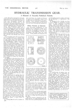
In its simplest form this transmission may be made almost as. a simple coupling, affording two changes of speed. kit is this type which we illustrate as exemplifying the principle, but avoiding the complication, which necessarily arises in a multi-speed gear. In that form it consists of aecylindrical casing, enclosing twoArotors, the chambers in which these rotors are disposed being separated one from,the other by a wall within the casing. The driving shaft is attached to the casing and the driven' shaft to one of the rotors, these two, therefore, being actually the driving and driven rotors of the transmission. The other rotor is mounted on a bush which projects through the cover of the casing, and is held stationary. This rotor, therefore, becomes, in actual fact, thestator of the gear.
As reference to the drawings will demonstrate, the whole arrangement is the equivalent of two vane pumps mounted in ' a single casing. The two pump chambers are not of the same size, the relative difference between them being actually a measure of the gees reduction which the transmission, in normal working, effect-s. In the drawing the pump of which the rotor is attached to the • driven shaft is twice the size of the other. The two are connected by two passages, one of which connects the suction sides of the pumps, the other effecting communication 'between their pressure chambers.
The operation, if we assume that the driving shaft rotates in the, direction indicated by the arrow, and that the driven shaft offers resistance to motion, is as..ieleows :—Movement of the casing causes the liquid within the driven rotor chamber to flow out into the other. If the two.pumps had been of the same size there would have been nothing to prevent this, and the liquid would simply circulate between the two. As, however, the second chamber is smaller then the other, the driven rotor is forced to rotate at a speed which, in comparison with that of the casing, is in inverse ratio to that' of the dimensions of the two chambers., In the 'example illustrated the ratio is 2 to 1, and the speed reduction is, thelefore, as 1 to 2. By interrupting the communication between the two chambers, thus preventing any flow of liquid at all, and at the same tune freeing the seater, a direct drive is obtained.. . . .
By building into one unit a number of A34
such couplings, any number of changes of speed can be obtained. Such a unit . is describeePandillustrated in the specification. Many hydraulic transmissions have been designed, but so far the results have not been anything like satisfactory.
Other Patents of Interest.
An interesting modification of the duplex type of two-stroke engine is described in No. 177,280 by B. D. Scott, Each pair of cylinders is arranged diagonalty to the crankshaft, and the two connecting rods bear upon the same crank. Trunk pistons are employed, the
two in one pair of cylinders drawing the explosive mixture through ports which .are controlled by a rotating valvet which itself serves as e pipe along 'Which the gases flow from the carburetter. The same pistons, on the upstroke deliver this mixture into another cylinder. It should be noted that the needloe-erankcase compression is obviated, notwithstanding the fact that. enhanced:induction and scavenging effects are obtained by the methods employed. High volumetric efficiency and fuel economy are claimed.
A gas-producer for commercial motor use is described in No. 177,236. It:has two grates, one above the other, and they are of truncated conical form, with the smaller end at the bottom. They are built into the firebrick lining so that ease of BRZeSs is assured. The patentee is T. H. Parker.
A selective type of change-speed gear for use with epicyclic gears is the subject of No. 171,109, by M. N. Viratelli. Each drain is provided with brake shoes., only one pair of which may be operated at one time.
Thencycle tractor, patented by C. R. Flitch Noyes, is a type intermediate between the usual general-purpose tractor
and the self-propelled garden cultivator. It is described in specification No. 177,302.
Birkigt, in No. 156,509, describes nevel Method of attaching 'steering levers to their respective swivelling •
axles. Instead of boring a' teem or parallel hole in the latter, and forming the levers with taper or Parallel shanks which will fit these holes he fortns tongues upon the levers, and cats grooves in the under surfaces of the swivelling axles. The grooves accommodate the tongues, and one or two bolts complete the attachment,.
Quite an interesting invention is described, . in No. 161,940, by Societe . Anonyme des -Aeroplanes G. Voisin. It is concerned with engine . lubrication, which, as the inventor points out, may he effected by pressure or splash. When the former is employed the distribution of the oil is under efficient control, until . the mechanism becomes subject to wear, when that efficiency is considerably impaired. Precisely the reverse is the case with splash lubrication, which presents no moving parts for wear, but which fails to ensure even and regular distribution of the lubricant. The lastnamed defect has also been characteristic, according to this inventor, of certain combinations of splash and pressure which have been tried; particularly do they fail to vary the distribution in accordance with the requirements of the engine as the power output rises and falls. The arrangement covered by this patent is such that tkhe distribution is better controlled, particularly as regardsthe last-named feature. The oil is lifted from the reservoir by a paddle wheel, which rotates with the crankshaft. This delivers into a chamber, whence egress to the connecting-rod dipping troughs is via a pair of concentric tubes, which are provided with ports, opposite the troughs and other parts requiring oil. The ports are opened or closed by the rotation of the outer tube, which Moves in accordance with movement of the throttle control.
The employment of grease cups, or' even oil cups, for the lubrication of various portions of a chassis " is attendant with many disadvantages, as will readily be appreciated by those operating motor vehicles as well as those having to do with the -upkeep thereof" is the sort of governing clause to specification No. 163,044, by B.' H. Skelly, which deals with an interesting system of chassis lubrication, embodying complete distribution of lubricant from a central reservoir and pumps. There is one pump to each oil pipe, but all the pumps are operated together by means of a ratchet lever, which, presumably. is reciprocated regularly, at prearranged intervals, such as daily, by the driver.