


War Department Subsidy Scheme, 1912.
Page 17
Page 18
Page 19
If you've noticed an error in this article please click here to report it so we can fix it.
Draft Specification for Petrol Lorries.
Particulars which Disclose an Absence of Touch with Commercial Motor Users.
1. Gc-licral.----13eneral conditions governing the grant of subsidy to vehicles suitable for War Department purposes.
The two main objects which the War Department has had in view in making out the following specification have been as follaws 0.i To make the manipulation and control of all vehicles the same, and
(b.) To minimize the number of spare parts which must be carried in the field, having regard to the number of different makes of vehicles of which the transport columns of the Army would he composed.
Only those lorries which comply in every particular with the terms of this specification and which are entirely to the satisfaction of the War Department will be eligible fur the grant of full subsidy after 1st July, 1912.
2. Pawn).Lorries must, in addition, be identical in every respect with one of the types which have been millmitred to the War Department for trials, have successfully passed the prescribed tests laid down for each class of vehicle and have in addition received the War Department certificate.
The manufacturer's drawing of these vehicles will be deposited at the War Office and should manufacturers be desirous of making any changes in design of their subsidized types they are to refer them to the Mechanical Transport Committee for approval.
The list, of such drawings is shown below.*
3. Corr-yin(' capacity.—The lorries arc to be of two classes
A.—To carry a useful load of 3 tons. R—To carry a useful load of 30 cwt.
F.ven with the heaviest of bodies that will be accepted by the War Department.
In referring to these hereafter they will be mentioned as Class A and Class B respectively.
In both cases in addition to the useful load specified the vehicles are to he capable of carrying two men on the driver's left on the front seat, as well as a fair kit of tools, spare petrol tins, etc.
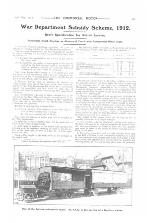
(NOTE.—The weight of the body work is not included in the useful load.) The following table of weights has been drawn nut to show the total gross weights that may have to be carried
Should any owners desire to fit bodies weighing more than the al1101111t9 shown in the above tables the matter would have to be reported, and if the weight WAS considered by the :Mechanical Transport Committee to be excessive, owners would be obliged to keep in addition for mobilization purpORPS another body of lighter weight which has been approved by the War Department.
Although it is anticipated that the majority of bodies obtained under the subsidy scheme will be at least some 7 or 8 cwt. lighter than the maximum figures shown, and although it is highly desirable that the body weights should be kept as low as possible. the total weights given above are those that may have to be carried by subsidized vehicles. It is therefore necessary that the vehicles should be capable of carrying them, and in the trials of type vehicles to he submitted as being suitable to earn the War Department subsidy, they are the figures that will be worked to.
The weight of the chassis should also be kept as low as possible consistent with ample strength.
4. Accessiliility.—As the subsidized vehicles when used in the field will have to be repaired as rapidly as possible without such conveniences as inspection pits. etc., the greatest care must be taken in the design to ensure thorough accessibility to all parts.
5. Piutv.tion porn dust and tr,:t._As vehicles when used. in the field will have to run considerable distances in convoy at close intervals over exceptionally dusty and muddy roads, and as time and opportunities will not often be available for cleaning them, all exposed moving parts must be protected
as well as possible by dust shields, and attention must be paid in the design to admit of easy cleaning.
As full protection as possible must be provided against water splashed up from below or otherwise finding its way on to any portion of the ignition system which might be rendered temporarily useless thereby.
6. Engine.—The engines in both classes are to be of the vertical four-cylinder internal-combustiun type, using ordinary commercial petroleum spirit (petrol) for fuel up to 760 specific gravity.
Class A.
Minimum cylinder bore to be 110 mm., or 4 inches. Minimum R.A.C. rating 30.0.
Class R.
Minimum cylinder bore to be 100 mm., or 4 inches. Minimum R.A.C. rating 24.8.
Cylinders to be cast in pairs. All inlet and exhaust valves to be mechanically operated. Valve stems to be enclosed by dust-tight covers, which must be so designed that they are readily removable and so that the accessibility of the valves and cylinder holding-down bolts is not affected. Inspection doors of ample size are to be provided in accessible positions at the sides of the crank chamber, so as to make the big end bearings thoroughly accessible for examination or for the tightening of big end bolts without removing the engine from the chassis. The inspection doors in all cases should be fastened by as few bolts as possible to facilitate their removal. Preferably they should be removable by undoing one bolt. The lower portion of the crank chamber to be capable of removal without disturbing the main bearings, SO as to facilitate examination of the latter.In the case of engines whose crank shafts run on ball bearings this will not be insisted on, so long as side doors are provided of sufficient size to enable the big end bearings to be examined. Engines must. be under a bonnet which is entirely removable, ride drawing No. 101c.
Vehicles with engines under the driver's seat will not be accepted.
7. Engine control.—All connections for throttle, governor, ignition, etc., to be by means of rods, not wire. 8. Governor—All engines are to be' provided with governors, which are to be set in so as to preventthe engine speed from exceeding 1000 revolutions per minute. 9. Ignition.—Ignition to be by high-tension magneto. In addition a secondsimilar magneto is to be provided as spare and carried suitably enclosed and in a protected place on the vehicle. Magnetos to be of waterproof pattern, failing which an effective cover of waterproof insulating material mug be provided on the working magneto in such a way as not to interfere with its accessibility for adjustment or cleaning. To enable the timing of the ignition to be readily set the flywheel is to be clearly marked to a fixed pointer with stamped directions, vide drawing No. 109. All magnetos to be arranged to fit on to a standard base, .ride drawing No. 108a, and to have a standard drive so that they may be interchangeable. Leads to the different cylinders should be of different colours to facilitate correct connections being made, and to be coloured as follows :—
Cylinder nearest radiator red, next green, next yellow. Cylinder nearest dashboard blue.
Print No. 108a shows the universal type of drive to be used with magnetos.
It will be noted that two types of fastening the magneto are provided for, namely, strap and set screws.
If a type of magneto is fitted in which the height of the spindle above the base is less than the 50 mm. shown in the drawing, it must be used with a packing piece, and should the height be greater than 50 mm. a packing piece must be provided and carried, so as to enable the standard magneto to be fitted.
If a magneto with automatic advance is fitted, the complete control must be provided for connecting up to the contact breaker of a standard magneto, should one have to be fitted as a replacement.
10. Starting handle.—Cranked portion to he interchangeable by haying end made as per drawing to fit on to shaft 1 inch square.
Length of handle, 9-inch centres. Vide drawing No. 107. 11. Radiators.—Vide drawing No. 101c.
Radiators to fit on to universal housing so that they will be interchangeable. This is effected by fixing them by means of trunnions near the lower end, and by a connection ibt the top. In order to avoid fouling the starting handle and to avoid fixing the dimensions of the frame, radiator must fit entirely above the frame.
Water inlet and outlets are shown of fixed sizes in fixed positions. Two outlets are shown so as to allow of connection being made on either side of engine as may be required. The remaining outlet is to be covered with a blank flange. The areas of the water passages in these have been made large enough for thermo-syphon circulation, and arrangements have been made for a flange joint to be made at these places.
The important dimensions in the drawing mentioned above are—
Height of trunnion above frame. Diameter of trunnion.
Distance between centre of trunnion and bonnet support.
Centre of inlets and outlets.
Diameter of outlets.
Fan to be fitted of sufficient capacity to prevent water from boiling during any of the trials of type vehicles. Radiators to be of the simplest possible form to allow of easy repairs, and to be of the vertical straight gilled tube type. Honeycomb radiators will not be allowed. A draincock with not less than 3-inch bore to be fitted to the lowest point of the water circulating system which must be so designed that it can thus be completely drained. Provision to be made to stiffen the frame to prevent the radiator from being subject to stresses due to the racking of the frame.
Radiator to be protected from possible injury in case of collision by a stout bar or tube placed in front and across the centre. See drawing No. 101c. 12. Bonnet —Bonnet to rest on angle or channel steel supports independent of the radiator. 13. Fuel supply and petrol tanks.—Vide drawing No. 110c.
Vehicles of both classes to be fitted with 30-gallon tanks. Gravity feed-supplemented if necessary by hand pressure pump on the steering column—to be employed. Position of hand pump (if used) is shown on print No. 1030. Tanks to be made of one of the following materials :—
Copper or brass brazed or, properly riveted and soldered: Lead coated steel.
Galvanized welded steel.
General arrangement of tank shown in drawing No. 110g. Petrol gauge of approved type to be provided, also gauze filter in filling hole, and means for cleaning out tank. The following are standardized :— Sizes of plugs.
Size of filling cap.
Filter.
• Position and size of inlet and outlet.
Diameter and length of tank.
The object being to make the tanks interchangeable, although some small variations may be permitted in the non-essential details.
Easily accessible filters to be provided in the supply system.
14. Lubrication and oil tanks.—Oil tanks to be of sufficient capacity to Last for a run of 200 miles with the vehicles fully loaded. Lubricators for engine and gearbox to be of such a type that they will work efficiently with the War Department oil which will be issued on mobilization.
The specification of this oil is given in a Separate appendix.
15. Grease cups. -The following sizes of grease cups only to be used All cups to be threaded 16 threads per inch (British Standard Automobile thread) and to be fitted with spring catch on cups and tee head or other device to enable them to he turned easily. (Messrs. Rotherham will manufacture these at the prices quoted in their catalogue for their existing standards.) Means of lubrication preferably grease cups to be fitted to spring shackel pins. 16. Change speed gears.—Both classes of vehicles are to be fitted with four speeds forward and one reverse. Gate change to be employed preferably of the type in which the lever is pivoted at the lower end. The arrangement nf the gate is as shown in the drawing No. 103a. Engines are to be provided with governors, which shall be A.) arranged that it shall not be possible to drive the vehicles of Class A at a greater speed than 16 miles per hour, and those of Class B at a greater speed than 20 miles per hour, even with the engine accelerated to its utmost extent. The
minimum reduction on top speed will then be (---) for Class A and t—) for Class B. The ratio between top and bottom gears in both classes is to be about 5 : 1 giving bottom speeds of about 3a and 4 miles per hour respectively. Reverse speed is nut to he
appreciably higher than bottom speed. All vehicles to be capable of ascending a gradient of 1 in 6 on the road fully aetded. Vehicles to be reasonably quiet on all their gears. 17. Hied axle.—The final transmission of power to the road wheels is to be by means of a live axle in which a bevel drive of approved design should be employed. Chain drive to hind axle will not be permitted.
As the standardization of hind wheels will entail difficulties in the standardization of brake drums and other parts, the only parts which are standardized are axle arms and beshes, which are to be the same in both classes of vehicle.
Axle arms are to be 3a inches in diameter, and of the type in which the wheel runs on the axle and in which the driving shaft does not carry any weight. Floating bushes of bearing bronze are to be used, a in. thick and 71 inches lung, vide &Awing Xe. 100a.
18. Tronsoniseion.—The power must not be transmitted through the real springs. Preferably an enclosed propeller shaft should be used with a combined radius and torque member ending in a universal joint.
When the propeller shaft is not enclosed guards are to be fixed in suitable positions round it, in order to prevent mei. dents occurring in case the shaft becomes detached or broken at either end.
19. Front ox/.—The bearings of the front wheels are standardized so as to make the wheels interchangeable. The stab arm is to be of the dimensions shown. Steering arms, etc., must come inside the lines indicated, vita. drawing No. 100c.
Design of front axle arms is the same for both classes of vehicle.
20. fareand clearance.—The minimum ertamd elearnnee using hind road wheels of 1050 mm. and 1620 nun. diameter respectively in the cases of Class A and Class B vehicles to be 12 inches measured with new tyres. A greater clearance than 12 inches would be preferred.
21. Wheels and tyres.—Wheels to befitted with solid rubber ta reki of the band type, and of the following sizes :—
For 1020 rum. and 1050 mm. tyres ... 881.6 mm. 9 ft. la in.
Fur 860 mm. by 900 mm. tyres ... 719.8 mm. 7 ft. 5a ins. the object. being to have two sizes only of wheel cenlass for the various sizes and sections of tyres. Should purchasers desire to have wider section tyres fitted,
they may fit 1030 by 100 mm., or 870 by 100 mm. tyres on the smaller vehicles, and 1070 by 140 mm. or 910 by 140 mm. tares on the larger vehicles, proraise/ the .1/onotsr of the .:teel centres remains the saute, but no increased subsidy can In given in this reepeet.
Front wheel stops must be provided to prevent the iyted front fouling the chassis.
111 tatter to ensure that tyres can be easily removed front any wheel centres with presses that may be need on the field. the flanges on the steel centres must not exceed 3-32 inch in heieht.
22. Son-skids for use in snow.—Supplies of these will be
borne by the War Department. To allow of their being
fitted, there must he a minimum clearance of 1.1, inches. mules all conditions. between the driving wheels and (rents or body, to allow of chains or ropes being fitted over the tares.
23. Control.—Shown on prints Nos. 103D and 103a.
Clutch pedal on left, brake pedal on right. Distance be tween centres, a:c.. shown on print No. 103o.
Pedals :o be marked " C " and " B," respectively. Travel of pedals to be about 3a, inches.
Accelerator pedal may be fitted if required. if provided, it is to be on the right of the brake pedal.
Au efacient clutch-stop to be provided.
Clutch and brake pedals to be provided with flanges, ,1 inch hiah, to prevent the foot from slipping off them. Means of adjusting slope of the top of pedal shotild be provided. Clutch and brake pedals are to work independently of each ether, aud to be fitted with springs of such a strength that the drivers can keep their feet on them continuously ii desired.
Other dimensiuns as per drawing. 103u (shows the position of the handle of change-speed lever in various gears. The maximum variation allowed from these is a inch ncutral, first, second, third, and fourth speeds; but in revetse position greater latitude will be allowed.
I.NOTE.—the above allows of considerable difference in the position of pivot of change-speed lever.)
Brake lever to be well away from change-speed lever, and to the right of it. Change-epeed lever to be 6 inches shorter
than brake lever, and to be finished off with circular knob. Brake lever to have plain cylindrical handle, in order to prevent any confusion arising as to which is which of the two levers. 1'OS16.0;13 Of levers with reference to driver are shown in drawing referred to.
Cate chaage.speed.—Two slots and two selectors only are to be fitted, the reverse being a continuation of the first
speed-slot. ...arrangements of slots to be as shown on drawing. Gear positions to be marked. Safety catch on change-speed lever to be fitted for reverse, Side brake lever to push on.
24. Levers for throttle and ignition.—Both to have their movement independent of that of the steering column, and to be placed underneath and to the right of it, as shown in taint No. 103o.
Both levers to move forward to increase speed of engine. Both levers to move on a rack and to have plate marked so
as to show what their movements will effect.. Muvement of each lever to be 90 degrees, the handles being at right angles to the main axis of the vehicle when in the centre of their travel.
'rhrottle may be operated by hand lever only, or by hand lever combined with foot accelerator, in such a way that on releasing the foot accelerator the throttle returns to the position set. by the hand lever.
NOTE.—Arratrasentents fvii Co r 01 are. ill 11.qtra fed by -771-eans of a working model, which. is available for inspection by appointment. 111 the office of Secretary, Mechanical Tran4port Committee, War Office. 25. Steering.—To be so arranged as to give 76 degrees of movement to the front wheels, i.e., 38 degrees from normal position to maximum luck on either side.
To give this lock, two complete turns of steering wheel are to be made. (Relative movement of hand wheel and road wheel will be as 91 : 1.4
26. POI bearings.—In order to reduce to a minimum the sleek of spares to be carried in the field, ball bearings, when
used on any parts of the vehicles. are to be of the sizes described below, and to the dimensions aiyen in the catalogue af the Hoffman Manufactering Cf_illthany, Limited.
Other dimensions as per table in catalogue.
Roller bearinea not to be used.
The standard ball bearings supplied in magnetos are not included hi the above. ,
27. Thrust wetsltere.—Corecspontlint; to each of the above sizes there will be standardized a light type single thrust washer. 2-inch and 2L-inch medium type single thrust washers may also be used.
Dimeneions as per standards in Hoffmaies catalogue.
It should be noted that whereas the dimensions are fixed cm as being to one particular maker's sizes, the War Department does not wish to prevent other makes being used so long as they conform, to the sizes given and could be replaced in ease of failure by bearings to Hoffman's standard.
28. ,Serew threads.—British standard screw threads to be used throughout the vehicles, rale publications Nos. 21, 39 (which includes 20, 28. and 38), 34, 45, and 54 of the EngineerStaxidarde Committbc: 29. universal joints.—tniversal joints (where exposed) and steering joints must be protected with leather covers. 30. Knuckle joints.—Knuckle joints meet be made with hardened steel removable bushes and hard steel pins with Thaekera■ spring washers to take up side play or rattle. Pin is to be fitted with a dowel and to be of the size shown in drawing, so that the renewable parts of these joints may be interchangeable, g..ide drawing No. 104, which shows two siaes of joint.
31. atrokess.—Two brakes must be fitted, one hand and the othera foot pedal brake, the latter operating on propeller shaft. The brake operating on brake drums fixed to the