 1
1 2
2 3
3 4
4 5
5 6
6 7
7 8
8 9
9 10
10 11
11 12
12 13
13 14
14 15
15 16
16 17
17 18
18 19
19 20
20 21
21 22
22 23
23 24
24 25
25 26
26 27
27 28
28 29
29 30
30 31
31 32
32 33
33 34
34 35
35 36
36 37
37 38
38 39
39 40
40 41
41 42
42 43
43 44
44 45
45 46
46 47
47 48
48 49
49 50
50 51
51 52
52 53
53 54
54 55
55 56
56 57
57 58
58 59
59 60
60 61
61 62
62 63
63 64
64 65
65 66
66 67
67 68
68 69
69 70
70 71
71 72
72 73
73 74
74 75
75 76
76 77
77 78
78 79
79 80
80 81
81 82
82 83
83 84
84 85
85 86
86 87
87 88
88 89
89 90
90 91
91 92
92 93
93 94
94 95
95 96
96 97
97 98
98 99
99 100
100 101
101 102
102 103
103 104
104 105
105 106
106 107
107 108
108 109
109 110
110 111
111 112
112 113
113 114
114 115
115 116
116 117
117 118
118 119
119 120
120 121
121 122
122 123
123 124
124 125
125 126
126 127
127 128
128 129
129 130
130 131
131 132
132 133
133 134
134 135
135 136
136 137
137 138
138 139
139 140
140 141
141 142
142 143
143 144
144 145
145 146
146 147
147 148
148 149
149 150
150 151
151 152
152 153
153 154
154 155
155 156
156 157
157 158
158 159
159 160
160 161
161 162
162 163
163 164
164 165
165 166
166 167
167 168
168 169
169 170
170 171
171 172
172 The Isolation of Fluid-operated Brakes
Page 136
If you've noticed an error in this article please click here to report it so we can fix it.
A Resum6 of Recently Published Patent Specifications
MEANS by which hydraulic brakes may be kept in' the "on" position when the operating pressure is relieved, are shown by W. L. Avery, The Blue House, Thorley, Bishop's Stortforcl, in patent No. 405,073. The principle used is the interposition of a valve in the pipe line which normally remains closed, but is opened mechanically when the brakes are being applied or released.
The drawing shows a cylinder (1) Which supplies the working pressure; the piston being operated by a bellcrank (6) and an arm (5), the latter being connected to the brake lever. The pipes to the brake are taken from :paces (2) which are separated from the cylinder by small valves (3). These valves are operated by a camshaft (4), which in turn is worked from the arm (5). Thus it will be seen that the operation of the lever opens the valves, forces the .iluid to the pipe lines, and then closes the -valves, isolating the brakes not only from the cylinder, but from each other.
• The specification describes also dualoperation details for front and rear brakes, and, in addition, modifications for applying the system to aircraft brakes
claimed is shown in patent No. 404,943, submitted by F. Perkins, Ltd., and C. W. Chapman, both of 17, Queen Street, Peterborough.
The design calls for the camshaft to be located just below the cylinder head. The valves are operated by rockers, which are in turn worked by adjustable tappets located in the ■cylinder head. Push rods are rendered unneces sary by reason of the sitall distance between cams and rockers. This design permits the whole of the valve gear to come clear away with the Cylinder head, leaving the pistons and camshaft open to inspection.
A New Design a silencer.
T'THAT the method employed surpasses all those hitherto used, and that complete noiselessness is attained, are the comprehensive claims made by Daimler-Benz A.G., Stuttgart-tintertiirkheim, Germany, in a. specification (No. 404,962), describing a new design of silencer. The basic principle of the invention consists of the division of the incoming gases into two streams, each of which is led to an end of the silencer, and projected along a helical path towards the middle. The action is that of one stream of gas screwing into the other, their kinetic energy being neutralized thereby. Having travelled the length of the silencer, the gases pass into an annular space, whence they can escape to the atmosphere.
Servo-brake Refinements.
1IIAORE delicate control and simAVIplicity of conversion of existing brakes are claimed for patent No, 404,639, submitted by M. E. Johnson, and Feeny and Johnson, Ltd., 134, Ealing Road, Wembley. The usual type of vacuum-bellows has one end fixed to the frame of the vehicle, whilst the other moves the brake rods. The brake pedal, in addition to operating the vacuum valve, usually applies a force direct to the brake rods, apart from the servo action.
In this invention, however, the bellows and valve form a selfcontracting unit positioned in the rod between pedal and brake, a pivot being the only connection to the frame of the vehicle, so that the re
aclion is taken by the pedal. This gives the driver that sense of " feel " which is so desirable in brake operation.
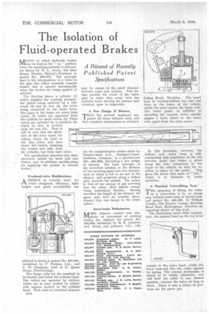
A Practical Valve-lifting Tool.
THE operation of lifting the collar on a valve-stern is by no means easy withoitt some form of special tool, and patent No. 404,432, by William Tomlin, The Eastern Garage, Berridge Road East, Nottingham, describes an ingenious device of this kind.
The illustratioti needs little explanation, the pointed head on the top lever centres in the valve head, whilst the lower fork-end lifts the collar against its spring. The ratchet mechanism is stated to be widely adjustable, and will hold the collar in any desired positiOn, whether the valve be long or short. There is also a choice of positions for the pivot pin.