


BETTER BRAKES FOR THE BIGGER LOADS.
Page 12
Page 13
Page 14
If you've noticed an error in this article please click here to report it so we can fix it.
The Problem of Providing Efficient Brake Application Through a Flexible Coupling Rendered More Important by the Introduction of the Tractor Lorry.
SO FAR as concerns the brakes of the ordinary four-wheeled lorry, there has lately been no complaint that they are not as efficient as they might be. In most designs, the diameter of the drums has been enlarged., more suitable materials have been produced with which to line the wearing surfaces, methods of adjustment have been improved, and so, for ordinary loads and ordinary hills, there is no urgent cry for improvement.
With the introduction of the large six-wheeler and the increasing use of trailers, however, a demand seems to be indicated for some improvement. In both of these cases the difficulty seems to be increased by the fact that the rear portion is not rigid with the front part of the vehicle ; consequently some elastic connection is rendered necessary if a brake is to be applied to the rear wheels of the six-wheeler, or to the wheels of the trailer.
The law calls for a brake to be fitted to all trailers, but many of such brakes merely carry out the letter of the law and not the spirit of it. Were they tested apart from the brakes on the power vehicle, they would, in many -.:ases, be found to be of little use.
In the case of the six-wheeler there is no need to consider what would happen in the case of a breakaway. In the first place, such an occurrence is almost impossible and, in the second place, if it did happen, the rear portion could not move after its separation from the front part. In the case of the trailer things are different, as a breakaway would mean something serious unless some automatic arrangement were provided to cope with such an occurrence.
The Needs of To-day.
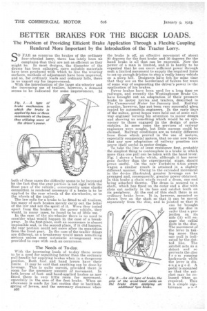
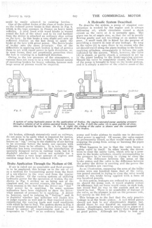
With the increasing loads of to-day there seems to be a need for something better than the ordinary pull-handle for applying brakes when in a dangerous position. Both foot and band levers have their limits. It may be said that anything cap be done by leverage. This is quite correct, provided there is room for the necessary amount of movement. In both levers of footand hand-applied brakes as now fitted there is very little room for movement, especially in the case of the foot brake. When an allowance is made for lost motion due to backlash, spring of levers, and the necessary clearance when B26 the brake is off, an effective movement of about 20 degrees for the foot brake and 30 degrees fnr the hand brake is all that can be expected. Now the power of a man is limited, and it is hardly to be expected that he can exert sufficient power through such a limited movement to supply the required force to set up enough friction to stop a really heavy vehicle on a steep hill. Designers. have felt for some time that they are on the borderland of failure for want of some way of augmenting the driver's power in the application of his brakes. Power brakes have been used. for a long time on railways, and recently the Vitestinghouse Brake Co. have brought out an adaptation of their pressure brake to motor lorries and trailers, described in The Commercial Motor for January 2nd. Railway practice, however, has not been very successful when copied by automobile engineers. In the early days of the motor, great hopes were held out of some railway engineer turning his attention to motor design and showing us something which would be an eyeopener to those engaged in the design of automobiles. In some eases the services of railway engineers were sought, but little success could be claimed. Railway conditions are so totally different from those which prevail in the use of motors, especially commercial motors, that no one now hopes that any new adaptation of railway practice can prove itself useful in motor design. To take the line of least resistance first, probably the simplest thing to contemplate is a brake in which more than one Pull can be taken with the hand lever. Fig: 1 shows a, brake which, although it has never gone farther than the experimental stage, should prove useful. On the new Yorkshire 6-ton steam wagon a similar result is attained in a slightly different manner. Owing to the extended movement in the device illustrated, greater leverage can be arranged and, consequently, greater power obtained. In this brake a chain winds round a drum, one end being attached thereto. The drum is secured to a shaft, which has fixed on its outer end a disc with slots cut radially in its face and ratchet teeth o.n its periphery. At the end of this shaft there is an ordinary brake lever. It is, however, mounted as shown free on the shaft so that it can be moved separately from the disc, and is jointed so that it can be brought near the disc in order that a pro= jection on its side (A) will engage the radial slots in the disc. The movement of the lever in taking more than one null is indicated by the dotted line. The ratchet acts as a detent and so prevents the disc fr om running backwards while the lever is disengage d. A pedal is motuited so that the ratchet may be released when so required. This is a simple cos, Fig. 2.—An old type of brake, the grip of the wood-lined cads on the brake drum applying an additional tyre brake. could be easily adapted to existing lorries.
One of the oldest forms of the class of brake known as the induced power brake is that shown in Fig. 2, which is the type common in France on heavy horse vehicles. A cord lined with wood blocks is wound round the hub of the wheel and to its end farthest from the driver is attached an ordinary shoe acting on the tyre. in this brake a very slight pull sets up sufficient friction on the hub drum to apply the brake at the tyre with great power. The Servo brake of to-day uses the same. principle. One of the difficulties in applying such brakes is that of getting them to act with equal power in both directions, as, in most forms, they are practically powerless when the hub is rotating in a backward direction.
Owing to the low pressure of the atmosphere, a vacuum does not see.rir to be a very convenient means of operating brakes for heavy vehicles, because such large areas of pistons would be required.
Air brakes, although dxtensively used on railways, do not seem to be quite what is required for lorries, as, with long pipes, there is likely to be what is known as" lag," owing to the elasticity of air having to be overcome before the brake can operate with sufficient force to be effective. it is true that this difficulty has been overcome by the introduction of specially designed valves in railway work, but it is doubtful whethersuch valves are suitable for a vehicle where a very large amount of neglect and careless usage have to be reckoned with
Brake Application Through the Medium of Oil.'
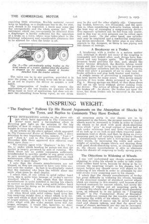
If air is ruled out as unsuitable and fluid pressure is to be employed, this brings us to the usc of oil as a medium_ for transmitting power from the front of a six-wheeler to the rear, and from the tractor to the trailer. Of the various systems of utilizing hydraulic power for the operation of brakes, the one shown in Fig. 3 strikes us as being one of the simplest and, for several reasons, the best. Among those reasons is the fact that the driver can " feel " what power he is applying. In some systems indicators have been employed to show the driver what amount of pressure be is applying. A driver is, however, used to judging by feeling," and it is doubtful whether any indicator will enable him to judge equally as well and to that required nicety, considering the varying loads and road conditions with which he has to deal. The system shown in Fig. 3 was originally designed for a legless driver and was found to answer all requirementsand to be as responsive to " feel " as an -ordinary brake.
A Hydraulic System Described.
To describe the system, a pump of simplest construction is worked by the engine and, is always delivering oil, which circulates round a short circuit as the valve at A is normally open. Tha pipes can be of ample size, so that the oil is merely flowing gently and not travelling .at an unduly fast pace. A small tank (13) is fitted for the purpose of providing a reserve in case of any leakage. So long as the valve (A) is open there is no reason why the oil should travel along the pipes leading to the brakeapplying cylinders, consequently it follows the path indicated by the arrows. When, however, the valve (A) is closed, or partly closed, a pressure is sot up in the pipes leading to the brake-applying pistons. Should the valve be completely closed, the full force of the pump is brought to bear on the brake pistons, arid it is simply a matter of the relative areas of the pump and brake pistons to enable one to determine what power is applied. Of course, the valve cannot be permanently closed, a,s.that would result in either stopping the pump from acting or bursting the pipes somewhere.
-What happens in use is that the valve forms a safety valve in itself: In other words, the driver tries to close the safety valve, which sets up a"pressure in the brake cylinders, exactly corresponding to the pressure he is exerting in trying to close the valve.. The difference between the areas of the brake piston and the valve is the difference between the power the driver is exerting and the power the brake cylinders are exerting. A3 an illustration, supposing the area of the br—ake piston were one hundred times that of the valve, one pound exerted in trying to close the valve would result in the brake being applied with a force of one hundred pounds.
In this system, leakages are reduced to a minimum, as, should the pump leak, it would slightly reduce its efficiency, but no harm would come, as such leakage would find its way to the suction and no oil would be lost. Thereis no possibility of leakage at the valve, as the plunger is not on the pressure side, but merely in the free oil. • This brings us to the fact that the only possible leakage is at the brake piston. A well fitted piston should not leak to any objectionable degree, but, should there be, any fearOof an appreciable leak there, a diaphragm could be employed in place of a piston. Diaphragms, however, have their bad as well as good points. Although not likely to leak and requiring little attention, flexible material cannot keep on bending, as a diaphragm has to do, for ever, and, should it be neglected, a burst may come one day unexpectedly and the whole system fail. The movement which can conveniently be obtained from a diaphragm is hardly sufficient for the operation of a brake on a lorry, where wear takes place in the frictional substances and considerable clearance has to be allowed for when the brake is off.
The valve can be in any position, provided it is near the pump, and the hand lever can be as usual, so as not to require the driver to acquire a now habit.
The compensation of brakes only ensures the application of the two brakes on separate wheels being equal in force of application, but does not ensure the retarding force being equal, as one drum
may be dry and the other slightly oily. Compensating brakes, however, are demanded, and the question is, when considering hydraulic brakes, which is the best way of arranging a, compensating device .1 Two separate cylinders can be fed from one source, and in this way an even pressure can be relied upon for each brake. On the other hand, one cylinder only may be employed and a mechanical compensating device introduced. The latter plan is one which appeals to the designer, as there is less piping and less chance of leakage.
A Breakaway on a Trailer.
A breakaway with a trailer is a serious matter and, although it should not occur if the coupling is reasonably well looked after, such things have happened and may happen again. The Westinghouse pressure brake provides for this, and, should the trailer become detached, the flexible tubing would break and this would bring into action the pressure in the auxiliary cylinders and the emergency valves, which will allow a pressure of air to come into the brake cylinders and stop both tractor and trailer.
A simple means of preventing a runaway trailer has been known for many years. This device simply consists of two brake shoes arranged as shown in Fig. 5. Strong springs are fitted, so that these shoes will act on thb tyres without power coming from the driver. The action of lifting the drawbar pulls the brakes off. As shown, the brakes act upon the tyres, but drum brakes can be operated in the same manner.