


APPARATUS FOR USE WITH HEAVY FUELS.
Page 58
If you've noticed an error in this article please click here to report it so we can fix it.
A Résumé of Recently Published Patent
Specifications,
'METRO GALASSO, .Guido Sa-rlo X and Fenerico Henuni.; all.of Naples, describe in .their. specification No. 245,173 a means for forming Charges for use with heavy fuels for internal.'combustion engines. A two-seated valve is employed to control the fuel and mixture. The valve is suction actuated, and the two seats are spaced apart, the fuel being controlled by the upper seat, the " mixture, which is made in the chamber between the, two seats, into which air bas access, being controlled
by the lower seat. One of the main features of the device is that the fuel is heated in hulk at a distance from the valve, the fuel is then admitted under pressure and is forced against and broken up by the co-acting parts of the valve.
The illustration shows on the left the means employed for heating the fuel, which consists of a chamber surrounded by a jacket for exhaust gases to elreulate round the fuel. A filter or strainer is provided to arrest impurities. The fuel passes from this chamber to the seating of the upper valve, where
its flow is checked by the valve. Its flow when the valve is open can be regulated by means of the needle valve shown. The valve is opened by the suction of the engine and is closed by means of a spring, not shown. Vent's are provided at the top of the chamber for the admission of air, which mixes with the fuel in the chamber. The perforated cup shown under the valve helps to vaporize the fuel and to break it up.
A Scotch or Sprag. .A SOMEWHAT crude a:aethod
stopping a vehicle from running. backwards, and of holding it when on hills, is shown in specification No: 245,202, T. J. Rees. The main point of this invention appears to lie in the fact that the sprag is spring-controlled and is thus able to accommodate itself to the variations of height of loaded and unloaded vehicles. The cord brings' the sprag in contact with the.tyre, which carries it into contact with the ground.
Steps for Emergency Doors.
sASIUEL GAGE and the London General Omnibus Co., Ltd., in their specification No. 244,197, show a fold ing. step for use with an emergency rear door. The step when folded up packs into a boot under the floor, and is held there by means of the rear door. When the door Is opened the step automatically unfolds and falls to the position shown in dotted lines. .
A New Form of Tyre.
GUIDO FORNACA, of Turin, shows in his 'specification No. 245,399 a form of tyre which can be used for smooth roads as an ordinary • rubber tyre, as shown in the left-hand lower view, oiv can be used as a straked tyre suitable for travelling over loose ground.
-.The tyre is made in sections, each section having a rubber-faced side and a straked side. These sections are each held to the wheel by means of a pair of bolts, one at each end, so that by merely reversing the side presented to the ground the tyre can be used for hard or soft ground. The sections do not cover the whole surface of the periphery—gaps being allowed between them. The sections are, however, staggered so that the gaps do not interfere with the smooth running of the wheel. A Means. for Carrying Containers.
JAMES S. A. WALKER • and Walker Bros. (Wigan); in specification No. 243,828, describe a means for carrying a container, and a special form of container which is particularly adapted to the carrying of house refuse. The container' has two wheels suitable' for running on the road, and two' smaller wheels which enable it to be easily drawn up the inclined ramp shown. A power-actuated winding gear is used to draw up the container, 'and when in. place thelower portion of the ramp can be folded up as shown,
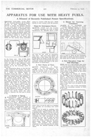
A New One-piece Cage for Ball Bearings.
THE cage of a ball bearing may .seem
to be an unimportant part of a motorcar, but there Lave been cases known in which thosecages formed of two parts which are riveted together have separated owing to the failiire of the rivets to hold them together.
The patent of Henry Ii'.
No. 244,046, covers a one-piece cage, as shown. This cage is stamped from a sheet in the form of a large ring ; it is then formed as shown in the upper view by pressing in dies. After the balls have been inserted in the bearing the cage is then bent over as shown in the lower view.
The use of a cage of this description enables the maxim*, number of balls to be used.