


THE PROBLEMS OF PIS'
Page 46
Page 47
Page 48
If you've noticed an error in this article please click here to report it so we can fix it.
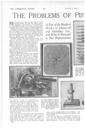
)N-RING MANUFACTURE MANY people may regard piston rings as easily produced articles, but that idea would .quickly be dispelled if they followed the manufacturing processes from the start to the finish, and were given an insight into the care necessary in selecting materials.
Pursuing our system of making readers familiar with the methods of production of the various components of motor vehicles, we give this week a detailed description of the research wbrk and the specially accurate machines required for the manufacture of piston rings. For this purpose we have selected the works of Hepworth and Grandage, Ltd., Bradford.
Although almost every metal has been tried, none seems to have been found so suitable as east iron. This may be due to the fact that east iron is slightly porous and has in it millions of minute flakes of graphite, which are, in themselves, a lubricant and which retain lubricating oil.
The manufacture of piston rings commences In the laboratory, where the selection of various grades of iron is made to farm a suitable mixture to give the right proportions of carbon, manganese, phosphorus, etc.
The next step in the procedure is the casting. Although many rings are made from what is known as a "pot," which is a cast-iron cylinder, while the mould is rotating at such a speed that all the metal is thrown by centrifugal force against its walls, no core being nsed, Hepworth and Grandage, Ltd., pins its faith mainly to rings made each from a sepa
rate Casting. To suit the requirements of customers the company manufactures both
• these single-cast rings and pot-cast rings.
All the iron used for single-cast rings is melted in crucibles, the process being the same as that employed for making the finest steels. Fig. 1 shows one of the castings, as it leaves the mould, and depicts 72 rings cast at one pouring, the central stem feeding the 12 layers each of six rings.
Fig. 2 shows one of the moulds, where the impression a six rings and the passages which connect them to the central stem can be seen in the sand. Twelve of these moulds are piled one on the top of another, as illustrated in Fig. 3. After pouring, and when the metal has been allowed to cool, the sand is broken
B32 away and the casting shown in Fig. 1 appears. The rings are then separated from the stem and are ready for machining.
The next operation is to rough-grind the inner portion of the ring, this being done merely to remove the scale, and is not relied upon to produce an accurate inside dimension, After this, the ring is carried
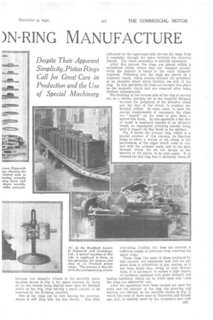
between two abrasive wheels in the specially made machine shown in Fig. 4, the space between the faces of the two wheels being slightly more than the finished width of the ring, thus leaving a small amount to be removed by the finishing machine.
One of the rings can be seen leaving the machine, where it will drop into the box shown. The slide indicated on the right-hand side carries the rings from a magazine through the space between the abrasive wheels. The whole procedure is entirely automatic. After this process the rings are placed within a cylindrical chuck, where they are clamped axially, while the interior is bored to the exact diameter required. Following this, the rings are placed on a magnetic chuck, which rotates beneath the periphery of an abrasive wheel which finishes one side of the ring. In this oration the rings are brought into place on the magnetic chuck and are removed after being finished automatically.
The finishing of the reverse side of the ring is carried out on a similar machine set to the required distance between the periphery of the abrasive wheel and the face of the chuck, to produce the finished article. In some cases, to meet the special requirements of customers, the rings are "lapped" on the sides to give them a mirror-like finish. In this operation a fiat disc of metal is employed instead of an abrasive wheel, an impalpable polishing powder being used to impart the fine finish to the surface.
Fig. 8 shows the scraper ring, which is a special product of this concern, its function being to effect a saving of oil, owing to the narrowness of the edges which come in contact with the cylinder walls, and to the Slots through which the oil can escape to the interior of the piston, to be used again. It is claimed for this ring that it definitely cures all over-oiling troubles, hut does not +prevent a sufficient supply of lubricant from reaching tho upper rings. These rings, like most of those produced by this concern, are separately cast, and are not made from a cylindrical, or pot, casting, as it has been found that, owing to their slender form, it is necessary to ensure a high degree of hardness combined with great strength and lasting resiliency, which can be relied upon only when the rings are separately cast.
After the operations have been carried out upon the sides and the interior of the ring, the grooving and slotting are effected on the machine shown in Fig. 5, which like most of those used by Hepworth and Grandage, Ltd., is entirely made by the company's own tool
manufacturing depar linen t. Machines made for ordinary purposes would not be so
efficient. Twelve rings are placed side by side on a mandrel, w ii i cli rotates while 12 cutters form the grooves, those pro-. (hieing the central groove being moved, at intervals, towards the centre until they break through, thus forming the slots. These, when in use, allow the Oil to pass through the ring.
Besides the manufacture of piston rings, the company produces large quantities of pistons of various light alloys and of cast iron. The machines and methods employed in the production of these components are of fairly well-known types, consisting of special lathes, centreless grinders, also lapping machines which produce mirror-like surfaces on the gudgeon.
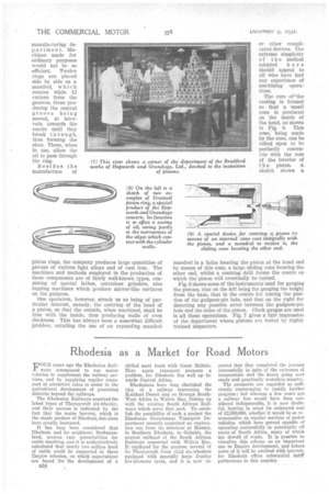
One operation, however, struck us as being of particular interest, namely, the centring of the head of a piston, so that the outside, when machined, shall be true with the inside, thus producing walls of even thickness. This has always been a somewhat difficult problem, entailing the use of an expanding mandrel or other complicated devices. The extreme simplicity of the method adopted her e should appeal to all who have had any experience of machining operations.
The core of"the casting is formed so that a ',small cone is produced on the inside of the head, as shown in Fig. 9. This cone, being made by the core, can be relied upon to be perfectly concentric with the rest of the interior of the piston. A sketch shows, a mandrel in a lathe locating the piston at the head end by means of this cone, a large sliding cone locating the other end, whilst a centring drill forms the centre on which the piston will eventually be turned.
Fig. shows some of the instruments used for gauging the pistons, that on the left being for gauging the height from the base, that in the centre for testing the position 0 the gudgeon-pin hole, and that on the right for detecting any possible error between the gudgeon-pin hole and the sides of the piston. Clock gauges are used in all these operations. Fig. 7 gives a fair impression of the department where pistons are tested by highly trained inspectors.