


A NOVEL CHANGE-SPEED GEAR.
Page 32
If you've noticed an error in this article please click here to report it so we can fix it.
A Résumé of Recently Published Patents.
A change-speed gear which has at least the charm of novelty is referred ,to in specification No. 164,889 by W. J.
Paterson. It may be described as a glorified' forth of Archimeciean drill, in which the engineiis made to reciprocate the nut of the drill, while the spindle, which is caused to revolve in one direction.only, transmits the drive to the rear
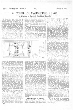
wheels of the vehicle. By altering the throw of the lever which transmits the reciprocating motion to the nut, alterations in gear ratio are obtained, infinite in variety,"from a neutral position to a maxim um depending 'upon the i arrangement of the gearing itself. The two illustrations which appear on this page•shew,s on the one hand, the arrangement of-the reciprocating motion and the method whereby the length of throw is controlled by the driver of the vehicle; and on the other the. Arehimedean drill section of the transmi.ssion, whereby that reciprocating motion is transmitted to a revolving one
We will deal with the latter portion first. Referring to the illustration, the central shaft is the revolving one and corresponds roughly to the clutch shaft of an ordinary car, except that there is no need for the interposition of a gearbox between it and the rear axle. This shaft is incapable of movement longitudinally, and has mounted on its inner end a gearwheel which is keyed to it, and which is actually in engagement with two other wheels which appear on 'the drawing to he one above and one below. These latter wheels are mounted _on. roller bearings with thrust ball races Their hubs are in engagement with+ spindles upon which are cut threads similar to those,of an Architnedean drill. One spindle has a right-hand thread, the:other•a left. The piniees are so arranged that they are capable of revolving on their hubs in one direction only. The spindles are carried by a slide which, at the point marked L, is coupled with a reciprocating device to which we shall refer later. As this slide is drawn in one direction, the threads. on the spindle cause•the hubs•of the two pinions to revolve, one in one direction, the other in the other. Owing to the free wheel arrangement, however, only one of the pinions is compelled to revolve with its hub, and as it does so it transmits power to the !central shaft. On . the return B26 staake, the direction of motion of the hubs is reversed, and the alternate pinion eoutinues to drive the central shaft in the same direction as before. • It is in this manner that the reciprocatory motion is., transformed into the revolving one.
• It will be understood that the longer the stroke of the slide thomore rapidly will the final drive shaft revolve, so that if the engine speed be kept constant, the gear ratio between engine and final drive shaft may be xaried by altering that length of stroke. This variation is effected in the following manner.:—Referring, to the other illustration' the pin marked "L " corresponds to the one similarly 'marked on the other diagram. The circular figure
to the left of the sketch represents the engine flywheel. As it revolves, it reciprocates the vertical lever which appears close to it to the extreme positions indicated by the dot and dash lines on the drawing. With the levers and the connections arranged as shown in the sketch, it will be understood that the point L will reciprocate approximately to the same extent as the engine crankpin; this is practically the top gear position.
If the change-speed ,handle, however. which appears at the top right-hand. portion of the sketch, be moved over to the !eft, it will lower the end of the coupling rod which connects the pin L with the reciprocating mechanism, bringing it nearer the fulcrum, lessening its travel, and, therefore, reducing 'the number of revolutions which ' the final drive shaft will make 'per revolution of the crankshaft. At the same time, owing to the increase in the effective leverage which this gives to the engine crank the propulsive power exerted by the transmission increases. This modification in the gear ratio may proceed. until the outer end of that coupling rod which is attached to L coincides, with the fulcrum of the rocking lever ; when that position is reached no movement whatever will be transmitted, and the free engine will be reached.
Other Patents of Interest.
The Cleveland Tractor Co. describes a simple form of dry air cleaner in specification No. 140,818. The intake pipe to the carburetter is produced forward to a point just behind the radiator fan, where it is enlarged. The enlarged end is turned hack so as to form a deep lip: The pipe, however, is still continued for a short distance, the material of this continuation, however, being comparatively fine gauze, and it is then capped by a conical metal piece, the apex of which points towards the radiator. Surrounding this again is a double truncated cone shaped as a venturi orifice. It is claimed that dust-laden air enters this venturi, and, travelling past the conical end of the inlet pipe, carries the dust with it, and that the engine suction only withdraws, from this. current, dust-free air, the dust itself 'being carried away owing to its greater inertia. The return lip on the end of -the inlet pipe is designed to prevent .eddies of this dust-laden air entering that pipe. • .
The principal features of the friction clutch, which is described in No. 146,866 by E. Bugatti, is the method whereby the clutch itself, which is of the disc type, is caused to engage or disengage. The two portions of the clutch are separated by the balls of the thrust bearing, the races of which, on the faces of which the balls are in contact, incline towards one another. There-is a third surface upon which the balls met, this being the tapering exterior of the sliding collar. When the collar is knshed inwards, as the result of depressing the clutch pedal, the balls are forced outwards and separate the two portions of the ball race, thus bringing the friction discs into close contact one with another.
The chief object of the arrangement of change-speed-gear abd control mechanism, . which is described by the Italian Fiat Co. in No. 154,874, appears to be that of preventing waste of oil from the gearbox or its escape on to the roadway. For this purpose the gearbox is cast. in two comnartments, of which the inner one actually contains the gear and any necessary lubricant, while the outer serves to cover the change-speedgear, and, in particular, those rods, etc., which must of necessity protrude from the gearbox.
No. 156,072, by C. A. C. Rispaud, describes a device for extracting stones and other foreign matter from between twin pneumatic tyres. It consists of a spring-controlled finger, which is disposed so that it lies between the two tyres, and extracts most of the foreign lib:lies which get between them before they have time to become embeddeld in position. In the event of it being unable to extract One of them, a curiceis clicking noise is set, up, thus attracting the driver's attention to the matter.
A rather intere,sting invention is disclosed by C. Burrell and SODS, Ltd., i. 164,932. It refers to the construction of steam engines, and indicates a method whereby the need for valve gear may be eliininated, and the piston caused to operate its own valve at each end of its stroke.
No. 165,136, by A. V. Roe, describes a built up, semi-solid tyre composed of. inverted cups of rubber, reinforced by Metal thimbles'