


A Sliding-vane Hydraulic C - lutch T HE idea of employing some form
Page 41
If you've noticed an error in this article please click here to report it so we can fix it.
of hydraulic pump as a part of the automobile transmission system is almost as old as the industry, but an application of this principle which has been invented and patented by Mr. IL CA Lee, D.F.H., A.M.I.E.E., 6, Boileau Road, Ealing, London, W.5, is, we believe, quite new.
A sliding-vane-type pump is, in this case, used as a clutch, and a development of the scheme is to incorporate such a clutch, which is compact, in each gearwheel on the main shaft of a gearbox, the layshaft wheels all being in constant mesh with their fellows. By this means any pair can readily be selected by engaging the appropriate clutch, by sliding axially, step by step, the main shaft.
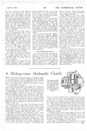
An accompanying drawing shows the design of the clutch. It will be seen that the vane works in a guide housed in a slot in the driving shaft, the eccentric housing forming tlap driven member. Provision is made for sliding the shaft lengthwise, and, in addition, the vane and guide can move axially in their slot.
On each side of the vane there is an oil groove-around part of the shaft's circumference, and the edges of the vane are bevelled for a part of their depth. The housing is kept full of oil from a channel in the shaft, the supply being maintained by a spring-loadedplunger. A locking device gives a positive drive when the clutch is in.
The clutch functions in the following manner: When driving, the vane, fully extended, bears upon the oil, and as this cannot escape, rotation is imparted to the housing. Axial movement of the shaft then uncovers one of the circumferential grooves, permitting a restricted flow of oil from one side of the vane to the other. This allows the clutch to slip, the degree of slip being dependent upon the amount of shaft end movement. To disengage the clutch the shaft is shifted farther, sliding the vane, too.
Only when the vane is fully depressed is this possible, but li71 soon as it enters the shaft tunnel at the side of its housing, it is retained in that position and the shaft then rotates freely and independently of the driven member. When letting in the clutch the operation is reversed.
The object of the bevelling on the vane edges is to limit the effectiveness of the clutch to about. one-third of the angular movement of the rotor—to that part where the biggest area of vane is -exposed. Thus excessively high pressures are avoided.
A criticism of the device, which might be made, is that the torque transmitted to the driven .element will rise and fall from zero to maximurn at each revolution of the vane relative to the housing. Thus, a series of impulses will be imparted instead of the steady turning movement which should be a characteristic of a good. clutch.
This might be eliminated by employing two or more blades, if the difficulties so introduced could be overcome. B7