


The " Scientific " Mechanical Lubricator.
Page 22
If you've noticed an error in this article please click here to report it so we can fix it.
The efficient lubrication of all the internal parts of valves and cylinders which are used with steam at high pressures or with high degrees of superheat has always presented diffi(utties to engineers. Many ingenious devices have been preduceu from time to time ; most of them depend for their action on ratchet-driven pumps which deliver a measured quantity of oil at intervals of from 10 to 100 strokes of the piston. Quite a number of ratchet-driven devices with which we have had experience are extremely wasteful of the oil as well as being very inefficient as lubricators. and, for those reasons, many steamengine users still employ the oldfashioned condensation type of oiler. which depends for its action on the condensation of small qmintities of steam inside an oil-containing vessel, the condensed steam displacing a small but regular stream of oil to the valves so long as steam is admitted.
W. H. Willcox and Co., Ltd., of 23, Southwark Street, SE., has recently introduced a new mechanical lubricator that. is not dependent on either of the above two principles : it is known as the " Scientific," and is intended to feed the exact amount of oil required for each steaming stroke of the pistons of a steam engine, and to deliver the lubricant direct on te the valves and into the cylinders only so long as the steam valve remains open. Its inventor claims that it will maintain a constant and regularlytimed supply under varying (onditions of temperature and steam pressure, and that it will work equally well with either saturated or highlysuperheated steam.
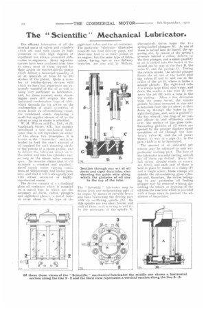
The device consists of a cylindrical glass oil container which is mounted on a metal base in which are the necessary oil ducts, valves, plungers and sight-feed glasses; a metal dome or cover closes in the tops of the
sight-feed tubes and the oil container. The particular lubricator illustrated herewith has four delivery pipes, amid these may lead to as many points on an engine, but the same type of lubricators, having one or two delivery branches, are also sold by Willcox,
The " Scientific " lubricator may be driven from any reciprocating part of an engine by means of suitable levers and links connecting the driving part with an oscillating spindle C.N). On this spindle are two shortlevers, and each of these, as it is swung to and fme by the movement of the spindle N,
alternatively drives home the two spring-loaded plungers M. As one of these is forced into its barrel, the opposing one, by reason of the spring s pressure behind a collar, follows up the first plunger, and a. small quantity of oil is sucked into the barrel of the second one by way of the duet B, the valve C, anti the passage 1). During the return stroke, the second plunger forces the oil out of the barrel past the valves E and ti, and out at the orifice of the jet H, where it forms a minute globule. The sight-feed tube is always kept filled with water, and down the centre a fine wire (I) connects the jet (H) with a, cone in the top casting. After a few deliveries from the pump barrel, the minute globule becomes increased in size and is detached from the jet piece; it then floats up through the water in the sight-feed glass, and, as it is guided by the fine wire (I), the drop of oil cannot adhere to, and ultimately cloud over, the surface of the glass tube.. Succeeding globules of oil which are. ejected by the plunger displace equal quantities of oil through the nonreturn valve. K. and the oil passes thence, by way of a pipe (L), to the part which is to be lubricated.
The amount of oil delivered per minute may be adjusted to suit any particular working part. The base of the lubricator is a solid casting, and all the oil duets are drilled. Above the ball valves, circular studs, or covers. are fitted, and each pair of these is held in place by means of a clamp (F) and a single screw; these clamps are outside the oil-containing glass cylinder and, therefore, the valves belonging to any particular oil feeding plunger may be removed without disturbing the others, or draining off the oil from the reservoir which is provided with a large sieve to prevent the admission of impurities.