


A ROAD-RAIL VEHICLE for
Page 46
Page 47
If you've noticed an error in this article please click here to report it so we can fix it.
'ERMANENT-WAY UPKEEP
FROM a railway company's point of view, there can be no doubt about the attractiveness of a road-rail vehicle for general maintenance work, owing to the wide adaptability of this type. Such a machine as that just produced by Karrier Motors, Ltd., Huddersfield, is obviously suited to service work generally and the maintenance of permanent way, which, cif course, involves carrying ballast, sleepers, sections of rail, points and the accoutrement for repairing and installing signalling apparatus. A relatively light machine capable of taking to the roads should be a great boon for work such as that outlined.
The main difficulty in making such a dual-purpose machine lies in adapting the road wheels to suit either road or rail conditions. Were it possible to run the machine only on a straight track without points, the task would be easy, but such ideal conditions never obtain in practice. It is, therefore, necessary to construct the axles in such a manner that the road wheels can be raised when running on the railway. In designing the road-railer under review, the Karrier concern has adopted an ingenious scheme which will later be described in detail.
A Modified Road-vehicle Chassis.
The basis of the design is a modified Karrier Victor C.Y.3-type chassis. Although normal control is used, the wheelbase dimension of 12 ft. is quite moderate, considering the fact that a useful platform space 11 ft. 2 ins, long by 6 ft. 7 ins wide is available. Hinged sides and a tailboard 1 ft. 9 ins, deep are provided, whilst the comfortable cab, which accommodates three or four men, is fully enclosed, the roof being 9 ft. above the ground.
A four-cylindered engine with a bore of 90 mm. and a piston stroke of 130 mm. transmits the drive to a fourspeed-and-reverse gearbox through the medium of a cone clutch, the final drive being by an overhead-worm-driven rear axle. • The vehicle is equipped with spring-loaded buffers and coupling hooks, and, although they are useful safeguards, it is not expected that the machine will have to be shunted or subjected to the bumping which is customary with railway rollingstock. Although of relatively light build, the structure is well braced.
The Frame Layout.
On to the forward ends of the frame sides two largediameter tubes are bolted, the tubes lying within the channels, to which they are attached by three bolts aside. A cross-tube joins these two longitudinal tubes with a further tubular structure built out to another cross-tube carrying the buffers and a central coupling hook. Running rearwards are further tubes whi4i. meet a flitched channel structure carrying the mudguards and the wheel-raising mechanism.
A somewhat similar form of construction is applied at the rear, the buffers and coupling hook being carried on a cross-tube, with suitable flitches and ties to the main framework of the chassis.
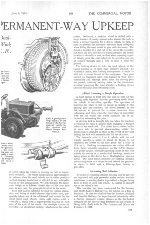
In designing a road-rail vehicle, there are one or two definite limitations which, to a large extent, regulate the layout. In the first place, the rail wheels have to fit the railway gauge, whilst the extreme width of the B32 axle cannot exceed the 7-ft. 6-in, maximum permitted by road regulations. The rail wheels on the Karrier are 4 ft. 8i ins, between flanges, whilst the front road-wheel track is 6 ft. la. in. and the rear track 6 ft. 4a ins., the overall width of the axle over the bearing caps being 7 ft. 5 ins.
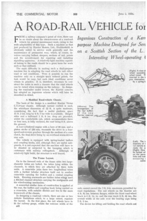
The device for lifting and holding the road wheels out of action when the vehicle is running on rails is ingeniously designed. The whole mechanism is approximately in balance when the road wheels are in either position, so that steering should not be affected to any noticeable extent by the arrangement. We will describe the frontaxle design as it follows closely that of the rear axle and, in any case, the principle involved is the same.
Each stub axle is extended beyond the normal dimension and, being of nickel-chrome high-tensile steel, adequately takes care of the additional load caused by the offset front road wheels. Each axle carries what is virtually a crank with a tapered-roller bearing on each side of the axis of the crank ; the crankpin carries an eccentric (an aluminium casting) which forms the wheel centre. Outboard, a skeleton wheel is drilled with a large number of evenly spaced holes around the hub to form a vernier location for a dowel, which, in turn, is used to prevent the eccentric structure from collapsing when lifting the road wheel to give rail clearances. The dowel is inserted in a slot cut in the end of the eccentric pin, then the hub and the rail-wheel assembly are locked in what is virtually a unit, so that, after removing a pair of driving pins, the road wheel on its eccentric pin can be rotated through half a turn to raise it from the ground.
The locking device to hold the road wheels in the raised position is of more than ordinary interest. To economize space, this locking arrangement is made to fold into a recess formed in the mudguard. Two pins carried on trunnions have eyes formed in their lower extremities and through these holes the driving pins are passed, entering locking holes in the aluminium eccentric carrying the road wheels); a locking device presents the pins from becoming loose,.
&Wheel Lowering a Simple Operation.
A light spring is built into the unit to hold all the moving parts together, thereby preventing rattle when the vehicle is travelling quickly. The operation of lowering the wheel is just as simple as raising it; the driving pinsare removed, the dowel inserted in the fulcrum-pin to prevent the eccentric structure from collapsing, and then, when the road wheel is concentric with the rail wheel, the whole assembly can be relocked by reinserting the pins.
A steering lock is brought into use when the machine is running on rails, a hinged plate engaging a flanged collar on the track rod. The collar has a rubber buffer at each side to prevent shock-loading, whilst the mechanism is arranged so that, in the event of any part failing, the lock will automatically fall out of action.
The rear-axle ratio is 0 to 1, which, with the rail wheels, enables a speed of about 50 m.p.h. to he attained; the lowest of the four gears has a ratio of 27.4 to 1. Braking arrangements are rather different from those normally employed on the C.Y.3 chassis. The pedal applies internal-expanding shoes in the rear wheels by means of a mechanical hook-up, assistance being given to the driver by a Westinghouse vacuum seri,o. The hand brake, intended for parking, operates contracting shoes on a drum located behind the gearbox. A starter is fitted and a 120-amp.-hour battery is provided.
Increasing Rail Adhesion.
To assist in obtaining efficient braking and to provide an improved rail grip generally under certain weather conditions, a sanding device is provided, a hopper being fixed in front of each rear wheel. A control is brought up to the driver's cab.
This machine has been constructed for the London and North-Eastern Railway Co. for service on a line in Scotland. It may be recalled that the London, Midland and Scottish Railway Co, experimented extensively with a Karrier passenger vehicle (known as the Re-Railer) designed on the lines of that described in this article, it being fully dealt with in The Commercial Motor on February 3, 1931.