


The Duplex Governor.
Page 17
Page 18
If you've noticed an error in this article please click here to report it so we can fix it.
Throttle Controlled both by Engine Speed and Vehicle Speed.
By HENRY STURMEY.
• In "the days of long ago," to
• wit, the later years of the last cen-Wry and the early ones of this, all car engines were governed gener-ally on the exhaust, by a centrifugal governor, which lifted the exhaust valve on the suction stroke ; and .very efficient the system was. later, when throttle control became universal, arid the mechanical sense of drivers was increased, the need for a governed engine in touring car work diminished considerably and the use of the governor was abandoned. About this time commercial cars were just beginaing to be made, and the ungoverned touring-car engine was pressed into service. As time went on, it was found that governors were, to some extent, desirable fitments for commercial-vehicle engines, and several governing devices were employed. Large numbers of commercial-vehicle engines are, 'however, still built to-day with ungoverned engines, not so much because they are not needed, but because drivers object to the control of their driving ; indeed, they often put them out of action when fitted—and also became they do not really fulfil all requirements. Particularly, it is found that the ordinary throttle goyernor, which comes into operation when the engine reaches a pre-determined speed, whilst preventing the over, speeding of the vehicle when running on the high gear, does not permit the engine to attain its most efficient speed and hence its full power when hill-climbing, or pulling through heavy ground on the low gear, and, furthermore, keeps the pace of the ear quite unnecessarily low on the low gears—and it is slow travel. on the low gears which wastes tune.
Governing by Vehicle Speed Only.
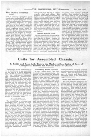
As a remedy for some of these Objections, governors have been tried in which the throttle is controlled, not by the speed of the engine, but by the speed. of the ear, the controlling mechanism being connected up with and operated by the transmission shaft. Such devices, whilst controllingvehicle speed, do not control the engine, except on high gear, as when the vehicle speed is reduced—as it is when running on low g ear—the engine speed is increased in proportion to the gear ratio ; and so unaer this system, the engine can be raced to destruction on the low gear if the driver is fool enough to do it, as the governor does not come into action until a vehicle -speed equal to the set speed one high gear is reached. In the "-Duplex Precision" governor, which has now been on the American market two years, and is to-day standardized as parte of the equipment of the " Jeffery," "Old Reliable " and "Harvey " trucks, and, where gov ernors are required, on the " Winconsin" engines, the control of the engine speed by.throttle is effected both by engine speed and car speed. The result is that wbitst the engine and car are both prevented being raced -when on high gear, -the en,
gine', whilst controlled as far" as maximum • speed is concerned and hence prevented racing, is allowed a higher speed when the car
is on the low gears, thus enabling the -full power .available in the engine to be utilized when hard. work is in question, and at the same time rendering possible a higher ear speed on the low gears than is obtainable with a constant-speed engine-controlled governor.
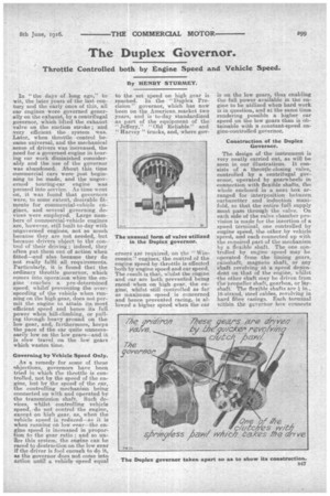
Construction of the Duplex Governor.
The design of the instrument is very neatly carried out, as will be seen in our illustrations. It consists of a throttle-closing valve, controlled by a centrifugal governor, operated by gearwheels in connection with flexible shafts, the whole enclosed in a neat box arranged for interposition between carburetter and induction manifold, so that the entire fuel supply must pass through the valve. On each side of the valve chamber provision is made for the insertion of a speed terminal, one controlled by engine speed, the .other by vehicle speed; and each connected up with the required part of the mechanism by a flexible shaft. The one cpntrolled by engine speed may be operated from the timing gears, camshaft,. magneto shaft, or any shaft revolving at a speed dependent on that of the engine, whilst the other shaft May be driven from the propeller shaft, gearbox, or laF, shaft. The flexible shafts are 16-strand, steel cables, revoly.ing in hard fibre casings. Each terminal wei.thin the geveenor hex cannects
with a one-way springless pawl clutch-unit, the means for actuating the pawl being a drag piece having sufficient adhesion for that purpose. The floating members of these clutches consist of gears, each in mesh with a third gear, operating the centrifugal mechanism, and the clutch engaging speed which is imparted to the centrifugal member is the higher of the two speeds, whether of the engine or vehicle. When the engine is free, the engine speed will control the governor. Thus, if we arrange that a maximum vehicle speed on direct drive will be reached at, say 800 r.p.m. of the propeller shaft, the drive being direct, the corresponding motor speed will be also 800 r.p.m. If the governor drive for Vehicle control is, -however, stepped up 25 per cent., the maxiMum governor speed of 1000 r.p.m. will be reached at the maximum vehicle speed which corresponds with 800 r.p.m. of the propeller shaft and engine. The governor drive from the engine for engine control could be so arranged that the engine would have to reach 1500 revs per min, before the governor speed reached 1000 and the engine was controlled. Thus, a higher engine speed is allowed by the governor when the car is running on the lower gears than when it is running on the high, but maximum engine speed is still controlled and limited.
Unusual Style of Valve.
In the construction of the valve, an important departure from current practice is made. Instead of the usual butterfly or full-width sliding mechanism, which takes an appreciable time to close and begins to cut down the supply–and hence the power—well before the maximum speed for which the governor is set has been reached, a grid system is employed, with very narrow openings, constructed in
two parts, each having. a latticed surface. One Member is fixed in the upper part of the valve chamber and is provided with elongated. slots running parallel to -the axis and the other part, with walls flaring from its under side upward. Below this fixed part is the movable part, having a corresponding series of slots, with walls flaring from its upper surface downward.. This movable part has an arc movement across the slots, and is supported on a substantial bearing and operated by a helical movement controlled by the governor, and the maximum travel from full open to full closed is but -fir in., so that when the governor comes into action, the cut-off is almost instantaneously done, thus allowingfull power to be developed to the last. The two parts of this valve have a ground fit, though they are not in contact. The movable part is 'held in open position by spring pressure, with stop screws limiting its movement.