


Flywheel to Enhance Governor Sensitivity
Page 36
If you've noticed an error in this article please click here to report it so we can fix it.
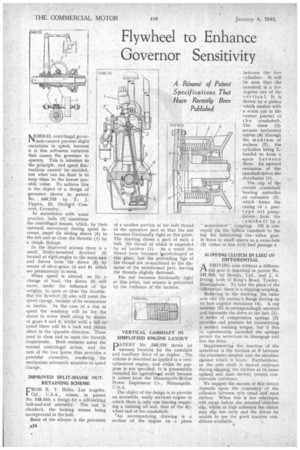
A Resume of Patent Specifications That Have Recently Been Published
MORMAL centrifugal gover111 hors cannot prevent slight variations in speed, because
it is this self-same variation that causes the governor to operate. This is inherent to the principle, and speed fluc tuations cannot beavoided, but what can her done is to keep them to the lowest pos sible value. To achieve this is the object of a design of governor shown in patent No. . 548,755 by T.. J. Tippen, 22, Orchard Crescent, Coventry. '
In accordance with usual practice, balls (3) constitute the centrifugal masses, which, by their outward movement during speed in crease, _impel the sliding sleeve (5) to the left and so close the throttle (I) by a simple linkage.
In the improved scheme there is a small 'freely-mounted flywheel (2) located at right-angles to the main axis and driven from the sleeve (5) by means Of ,skew-gears (4 and 6) which are permanently in mesh.
When speed is altered, as by a change of load, the sleeve (5) will move, under the influence of the weights, to open or dose the throttle. But the flywheel (2) also will resist the speed change, because of its momentum or. inertia. In the case of a rise in speed the tendency will be for the sleeve to screw itself along by Means of gears 4 and 6; whilst with a fall in speed there will be a 'rack and pinion effect in the opposite direction. These tend to close and to open the throttle ;respectively. Both motions assist the normal centrifugal action, and the sum of the two torces thus provides.a . powerful corrective, rendering. the mechanism extremely sensitive to Speed change.
IMPROVED SPLIT-SHANK NUTRETAINING SCHEME ROM E. T. Holtz, Los Angeles, Cal., U.S.A., comes, in patent No. 548,650, a design for a self-locking bolt-and-nut assembly. The nut is standard, the locking means being incorporated in the bolt.
Basis of the scheme is the provision A34 of a swollen portion of the bolt thread at the operative part so that the nut becomes frictionally tight at this point. The drawing shows a part of such a bolt, the thread of which is expanded by au i incision (I). As a result the thread form becomes liarrel-shaped at this place, but the protruding tips of the thread are re-machined to the diameter of the undeformed part, leaving the threads slightly flattened.
The nut becomes frictionally tight at this point, but seizure is prevented by the resilience of the incision.
VERTICAL CAMSHAFT IN SIMPLIFIED ENGINE LAYOUT
PATENT No. 548,176 shows an unusual location for the camshaft and auxiliary drive of an engine. The scheme is described as applied to a twotylindered engine, and whilst its purpose is not specified, it is presumably intended for agricultaial work because it comesfrom the Minneapolis-Moline Power Implement Co., Minneapolis, U.S.A.
The object of the design is to provide an accessible, easily serviced engine in which there is only one bearing requiring a running oil seal, that at the flywheel end of the crankshaft.
An accompanying drawing is a section of the engine on a plane
between the two cylinders. It will be seen that the camshaft is a few degrees out of the v-ertical. It is driven by a pinion which meshes with a worm cut in the central journal of the crankshaft. The cams (2) actuate horizontal valves (6) through the medium of rockers (7), the cylinders being Lheaded to form a space between them. An upward extension of the carlishaft drives the distributor (I).
The cap of the central . crankshaft bearing .embodies an extension (5), which forms the casing of a geartype oil pump, driven . from the , camshaft by a. "
screwdriver' coupling. Oil is conveyed via the hollow -camshaft 'to the top for lubricating the Valve gear. It. flows in small spurts as a cross-hole (3) comes in line with feed passage 4.
SLIPPING CLUTCH IN LIEU OF DIFFERENTIAL
ADRIVING axle without a differential gear is described in patent No. 547,824, by Bendix, Ltd., and j. S. Irving, both of King's Road, Tyseley, Birmingham. To take the place of the differential, there is a slipping coupling.
Referring to the drawing, the outer axle end (3) carries a flange liaving on its face angular serrations (4). A cap member (5) is correspondingly serrated and transmits the drive to the hub (1) . A series of compression springs (2) provides end pressure for transmitting a normal running torque, but if thisbe considerably exceeded the springs permit the serrations to disengage and
free the drive. ,
Supplementing the reaction of the serrations is the friction at 6 between the abutment Member and the shoulder against which it bears. Furthermore. as the axle shaft is moved endways during slipping, the friction at its inner splined end (not shown) creates considerable resistance.
We suggest the success of this device depends upon the constancy of the adhesion between tyre tread and:road surface. When this is low wheelspin will occur before the serrated—clutches slip, whilst at high adhesion the clutch may slip too early and the driver be unable to use the good tractive conditions available.