


APPLYING BRAKES BY FLUID PRESSURE.
Page 32
If you've noticed an error in this article please click here to report it so we can fix it.
A Resume of Recently Published Patent Specifications.
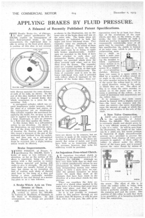
MHE Bcndix Brake Co., of Chicago, 1. in their patent specification No. 234,848, explain an arrangement of their fluid-actuated brake. In this arrangement, the right-hand shoe is able to swing en the fixed pivot shown. A portion of this shoe is not covered with fibrous material for some distancg at each of its ends, as shown. To the end of this shoe farthest from the fixed pivot is hinged a second brake shoe which terminates in a joint for the operating link.
A corrugated cylinder, which can expand lengthways under pressure, takes the place of a cylinder and piston, as the -corrugations net as diaphragms. This cylinder supplies the movement for applying the brake, for, as soon as pressure is applied by means of the foot to a large diaphragm, it sets up pressure in a fluid and thus applie.s the brake.
In this design there is a self-assisted action in one direction. As shown in the illustration, an anti-clockwise movement of the drum will have the effect of drawing the floating shoe with it ; this causes a pressure at the end of the anchored shoe farthest frau' its anchorage, and thus sets up a self-assisted action. Should the direction of the drum be reversed, only a slight.braking action would be effected,
Brake Improvements.
HENRI PERROT, of France, in specification No. 232,565, shows a brake of more or less ordinary construction, so far as the section of the shoes is concerned, being of channel section. with a flat portion to receive the fibrous material and having side walls to give it strength. He says that such shoes are usually formed of castings, but claims as an invention the fact of making such shoes of channel steel bent to the form of a shoe and having a piece, preferably metallic, attached to one end thereof as a mounting piece or as a cam follower.
A Brake Which Acts On Two Drums at Once.
ADOUBLE-ACTING brake is described in patent No. 231,890, by Lorenzo .0. Markham, of Olympia, in the State of 'Washington. In this arrangement, two drums are provided
e48 as shown in the illustration, one on the inner side of the brake shoes and one on the outer side. The brake shoes are duplicated as indicated in both the upper and lower left-hand views. Two expander cams are employed, one to each pair of shoes. The action of these expander cams is to force the brake shoes apart and, by so doing, to apply both brakes simultaneously. Anchorages are provided in the form of horn blocks attached to each shoe and rectangular blocks pivoted on studs. Springs are provided which draw the shoes towards each other, and so free them from the drums. The expander cams are coupled together by means of levers and connecting rods, so that both brakes are applied simultaneously. The form of expander used is seen in the lower right-hand view, and is provided with rollers where it impinges on the surfaces of the brake shoe ; these sur faces are shown to be concave, but no Mention is made of the reason for this. As depicted in both views, the shoes are merely flat strips of metal, and would have little or no transverse stiffness. We presume, however, that webs for stiffening would be provided.
An Ingenious Free-wheel Clutch.
AN ingenious free-wheel clutch is show n in the specification of J. C. W. Ilurnirey, No. 239,894. Although we have very little faith that we shall ever see a vehicle satisfactorily driven by any arrangement in which clutches transform reciprocating motion into rotary motion to form a main drive, we consider the present invention as being nearer the mark than Most of the attempts that have been made in the direction of a free-wheel clutch for this pu rpose.
When one considers the duty expected of a clutch when applied to the main drive, it is obvious that great wear must take place, and that all parts must be very heavily stressed.
As it is not possible to transmit power in this manner through an arc of more than 99 degrees, it will be seen that, when on top. gear, the 'rate of re ciprocation must be at least four times that of the revolutions of the road wheels, and that, On the return, or idle, stroke, the two elements of such a clutch are moving in apposite directions. consequently considerable wear of all parts may be expected. According to this specification the clutch is formed of an outer cone, which is part of the reciprocating member—a shaft on which a male cone is formed constituting the member to which continuous rotary motion is to be transmitted by means hi a number of reci procating i clutches. Between these two cones is a space which is filled by a number of rollers placed at an angle to the axis, as shown. When the outer member moves in the direction of the arrow the rollers tend to roll in a spiral direction, owing to the angle at -which they are set. The effect of this is to cause the outer member to mount on to the -inner cone and so cause a jamming of the rollers. A reversal of movement will immediately set the rollers free.
It is necessary that both cones should be formed with a slightly curved face--the inner one concave and the outer one convex—the curve depending upon the amount of angle at which the rollers are set relative to the axle of the :haft.
A New Valve Connection.
ANEW valve connection is outlined in the specification of James Perker, No. 242,202. This connection is extremely simple and should prove to be a very efficient means of connecting a tube to a valve. As will be seen from the illustration, the nozzle of the valve can be a plain one, but would perhaps be 'improved if slight circumferential grooves we7.:: provided to prevent the connection from slipping off when great pressure is applied. A thick collar of rubber, is .placed under the sliding barrel of the inner part, and is pressed against the miter flange by means of
the screw. The effect of this is to cause the rubber collar to bulge, both inwardly and outwardly, so that it forms a perfectly airtight seal between the engaging part and the nozzle. The position of this collar is such that there is no possibility of it becoming detached from the connection.