


Lightness and Strength in Wheels for Heavy Motor Vehicles.
Page 7
If you've noticed an error in this article please click here to report it so we can fix it.
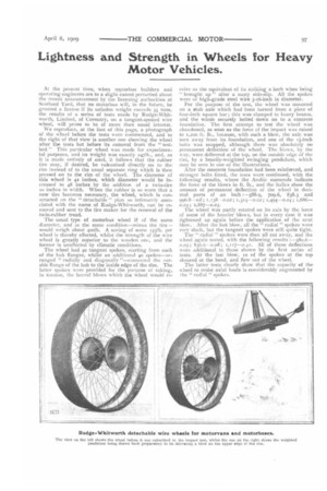
At the present time, when mptorbus builders and operating engineers are to a slight extent perturbed about the recent announcement by the licensing authorities at Scotland Yard, that no motorbus will, in the future, be granted a license if its unladen weight exceeds 3i tons, the results of a series of tests made by Rudge-Whitworth, Limited, of Coventry, on a tangent-spoked wire wheel, will prove to be of more than usual interest. We reproduce, at the foot of this page, a photograph of the wheel before the tests were commenced, and to the right of that view is another one showing the wheel after the tests but before its removal from the " testbed." This particular wheel was made for experimental purposes, and its weight was exactly 24711)., and, as it is made entirely of steel, it follows that the rubber Lire may, if desired, be vulcanised directly on to the rim instead of to the usual separate ring which is then pressed on to the rim of the wheel. The diameter of this wheel is 42 inches, which diameter would be increased to 48 inches by the addition of a twin-tire in inches in width. When the rubber is so worn that a new tire becomes necessary, the wheel, which is constructed on the "detachable " plan so intimately associated with the name of Rudge-Whitworth, can be removed and sent to the tire maker for the renewal of the twin-rubber tread.
The usual type of motorbus wheel if of the same diameter, and in the same condition—minus the tire-would weigh about 400lb. A saving of some 1331b. per wheel is thereby effected, whilst the strength of the wire wheel is greatly superior to the wooden one, and the former is unaffected by climatic conditions.
The wheel had 40 tangent spokes, starting from each of the hub flanges, whilst an additional 40 spokes—arranged " radially and diagonally "—connected the outside flange of the hub to the inside edge of the rim. The latter spokes were provided for the purpose of taking, in tension, the lateral blows which the wheel would re
ceive as the equivalent of its striking a kerb when being " brought up " after a nasty side-slip. All the spokes were of high-grade steel wire 3-16-inch in diameter.
For the purpose of the test, the wheel was mounted on a stub axle which had been turned from a piece of four-inch square bar; this was clamped to heavy beams, and the whole securely bolted down on to a concrete foundation. The first attempt to test the wheel was abandoned, as soon as the force of the impact was raised to 1,200 ft. lb., because, with such a blow, the axle was torn away from its foundation, and one of the ii-inch bolts was snapped, although there was absolutely no permanent deflection of the wheel. The blows, by the way, were delivered at the top, on the outside edge of the rim, by a heavily-weighted swinging pendulum, which may be seen in one of the illustrations.
After the ooncrete foundation had been reinforced, and stronger bolts fitted, the tests were continued, with the following results, where the Arabic numerals indicate the force of the blows in ft. lb., and the italics show the amount of permanent deflection of the wheel in decimal parts of an inch :-588.9, 709.6, 838.3 and 996.8--rii1; 1,138 0.02 ; I >314-0.02 ; 1,494-0.04; 1,686—
The wheel was partly rotated on its axis by the force of some of the heavier blows, but in every case it was tightened up again before the application of the next blow. After the last blow, all the " radial " spokes were very slack, but the tangent spokes were still quite tight.
The "radial " spokes were then all cut away, and the wheel again tested, with the following results :-580.6— o.o5; 836.6-0.08; All of these deflections were additional to those shown by the first series of tests. At the last blow, to of the spokes at the top sheared at the bend, and flew out of the wheel.
The latter tests clearly show that the capacity of the wheel to resist axial loads is considerably augmented by the " radial " spokes.