


A SELF-COMPENSATING SELF-ADJUSTING BRAKE.
Page 30
If you've noticed an error in this article please click here to report it so we can fix it.
A Résumé of Recently Published Specifications.
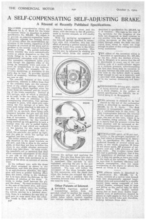
RATHER comprehensive claims are Made by L. C. Huck for the brake mechanism which he describes in patent specification No. 200,528. His object is to provide wrinenternal-expanding brake mechanism wherein the braking action will always effect the mostnefficaent•application of the brakes, regardless of the direction of rotation of the drum and regardless of the uneven wearof the brake shoes.' patent embodies means :whereby the shoes •atitornatically centre or adjust themselves so that the brake lining is, in' its worn condition, substantially concentric with the drum. This automatic adjustment takes place even though the opposite sides of the lining be unequally worn and, even if there be irregularities in the surfaces, brought about, for example, by inaccurate machining, or distortion of the parts due to heat. It provides against faults of assembly, whether the brakes are new or old. The essential features of this brake mechanism, wherein it differs from that of the orthodox type, are the arrangement of the release springs, -which pull the expanding •shoes together when the brake shoes are released, and the mounting of the brake camshafts. Instead of two springs, each of which is attached,at its ends, to the two shoes, there are, as may be -seen on reference to the accompanying illustration, four springs, arranged in pairs, with short pins separating the two springs of a pair, 'the inner ends being attached to the ends of the pin in each case. The pin is sup. ported by an eye-bolt, there being such clearance between the pin and the hole .in the eye-bolt as to allow the pin freedom of movement. This movement is restrained, ;.however, by the eye-bolt being screwed up into pnsitinn in such a manner that the pin is pulled tightly . into V slots in lugs which are mounted on the bracket for the brake 'anchor pins. The normal position is that in which the eye-bolts are pulled up tight, and the pins to which the springs, are attached, not free to mOve. The brake camshafts are semi-universally mounted in the usual brackets on the axle, and ride in slots in the anchor plate, so that they are free to follow the shoes in any slight circular movement which may take place. • In other -words, the camshafts are so mounted that they allow automatic adjustment of the shoes to One side or the other of the main anchor pin, when such movement is required of the shoes on account of uneven wear. In the ordinary way, with the drum and shoes arranged as shown in our 'illustration, and with the drum rotating in an anti-clockwise direction, the upper shoe will have a greater braking effect than the lower, owing to the tendency for it to turn about the,fulcrum, in the direction of rotation of the drum. It tends to wedge itself between the pin and the drum. No such tendency exists in the case of the lower shoe, and conicgnently in a vehicle where the braking, for the most part, is taking place with the vehicle moving in a forward direction, there is a tendency for ene shoe of each pair to wear more than the other. The reanlb is thae, after a time, the
134P
clearance between the shoes and the drum, with the brake in the off position, tends to become unequal, as will readily be realized. With the springing arrangement of the take-off springs specified in connection with this invention, this has the effect of causing a greater tension in one spring of a pair than exists in the other, when the brakes are in operation. This tension may be adjusted by slacking the eye-bolt which holds the central pin between the springs and applying the brakes. The pin then floats into such a position that the tension on the springs is equalized. The eye-bolt is then tightened, securing the pin in the new position with the tension in the springs equalized. The cam will follow the movement of the shoes brought about by this manoeuvre, with the result that when the brakes are released the shoes will take up such a position that' the clearance between them and the drum is the same for both.
Other Patents of Interest.
A RATHER ingenious method of transmitting motion from one sprocket wheel to another by means of a continuous row of balls contained within tubes which connect together two casings enclosing the sprockets is described in specification No. 220,804, by C. S. Gardner. The cups in the rims of the sprockets for the reception of the balls are staggered in their relation to one 'another -with the object of ensuring rolling movement of the balls. The tubes through which the balls are conveyed from wheel to wheel are large enough to allow of this rolling movement being continuous.
THE object of the invention which is described in specification No. 207,160, by the Soc. Anon. des Ateliers d'Aviation L. Beoguet, is to ensure that the oil is distributed to every one of the connecting rods of a multi-cylinder engine at a uniform pressure, notwithstanding the fact that there may be variation in the play between the rods and the shaft. The hole in the hollow shaft is made large enough to ant as a reservoir, and is provided with dippers which lift the oil to the various conneoting rod bearings.
SPEEDOMETER driving gear, capable of being mounted within the gearbox of a Ford chassis, is the subject of patent specification No. 220,875, the inventof being C. A. E.rogsgaard.
FUEL 'economy is claimed to be furthered by the use of the 'carburetter which is described in specification No.
220,680, by 0. Y. Imray. The float chamber is hermetically sealed, except for a calibrated hole in the cover. A tube communicates between the interior of the chaniber and the induction passage, the end of this tube, which is in the chamber, being reduced. The effect is to ensure that the pressure within the float chamber will be increased or decreased simultaneously with the decreasing or increasing speed of the motor.
METHYLATED spirit, of 95 per cent.
purity, is the principal ingredient of the fuel which is described by G. Scarsvelli in specification No. 206,147. A preferred formula of several which are given, is one which comprises 84 litres of the above spirit, 350 grammes of sulphuric acid and 1,200 grammes of calslum oxide. The inventor' claims that this fuel is perfectly uniform, that it has the appearance of distilled water, and that it does not smoke or leave any scale on the walls of the cylinder. Moreover, he Bays that it increases efficiency and reduces consumption, does not cause overheating of the engine' or attack the meta/ of which it is made.
THE silencer which is described in specification No. 220,808, by E. Wynn, consists of a central inlet formed with two diametrically opposed longitudinal slots and surrounded by a doubly conical inner casing composed of two conical frustra, arranged base to base and fitting on the central tube by their smaller ends. This doubly conical casing has at least three double longitudinal rows of perforations located in planes at right angles to that of the two slots in the central tube and, therefore, midway between those slots.