


MUST BE CON SISTENT
Page 37
Page 38
If you've noticed an error in this article please click here to report it so we can fix it.
main designs of the R.P. automatic brake adjuster, the earlier designs having been improved in the light of running experience.
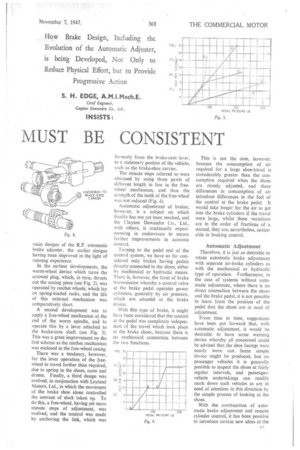
In the earliest developments, the worm-wheel device which turns the screwed plug, which, in turn, thrusts out the nosing piece (see Fig. 2), was operated by ratchet wheels, which lay on spring-loaded racks, and the life of this external mechanism was comparatively short.
A second development was to apply a free-wheel mechanism at the end of the worm spindle, and to operate this by a lever attached to the brake-cam shaft (see Fig. 3). This was a great improvement on the first scheme as the ratchet mechanism was enclosed in the free-wheel casing.
There was a tendency, however, for the lever operation of the freewheel to travel farther than required, due to spring in the shoes, cams and drums. Finally, a third design was evolved, in conjunction with Leyland Motors, Ltd., in Which the movement of the brake shoe alone controlled the amount of slack taken up. To do this, a free-wheel, having yet more minute steps of adjustment, was evolved, and the control was made by anchoring the link, which was formerly from the brake-cam lever, to a stationary portion of the vehicle, such as the brake-shoe carrier.
The minute steps referred to were obtained by using three pawls of different length in line in the freewheel mechanism, and thus the strength of the teeth of the free-wheel was not reduced (Fig. 4).
Automatic adjustment of brakes, however, is a subject on which finality has not yet been reached, and the Clayton Dewandre Co., Ltd., with others, is continually experimenting in endeavours to secure further improvements in accurate control.
Turning to the pedal end of the control system, we have so far considered only brakes having pedals directly connected to the shoes, either by mechanical or hydraulic means. There is, however, the form of brake transmission whereby a control valve at the brake pedal operates power cylinders, generally by air pressure, which are situated at the brake drums.
With this type of brake, it might have been considered that the control at the pedal was completely independent of the travel which took place at the brake shoes, because there is no mechanical connection between the two functions. This is not the case, however, because the consumption of air required for a large shoe-travel is considerably greater than the consumption required when the shoes are closely adjusted, and these differences in consumption of air introduce differences in the feel of the control at the brake pedal. It would take longer for the air to get into the brake cylinders if the travel were large, whilst these variations are in the order of fractions of a second, they are, nevertheless, noticeable in braking control.
Automatic Adjustment Therefore, it is just as desirable to retain automatic brake adjustment with separate air-brake cylinders as with the mechanical or hydraulic type of operation. Furthermore, in the case of systems without automatic adjustment, where there is no direct connection between the shoes and the brake pedal, it is not possible to learn from the position of the pedal that the shoes are in need of adjustment.
From time to time, suggestions have been put forward that, with automatic adjustment, it would he desirable to have some warning device whereby all concerned could be advised that the shoe facings were nearly worn out. Some simple device might be produced, but on passenger vehicles it is generally possible to inspect the shoes at fairly regular intervals, and passengervehicle undertakings can readily mark down such vehicles as are in need of attention in this direction by the simple process of looking at the shoes.
With the combination of automatic brake adjustment and remote cylinder control, it has been possible to introduce certain new ideas at the brake-pedal end. A brief review of the history of development of braking control is desirable in order to appreciate what these latest phases offer.
In the earliest days of passenger vehicles, when only two-wheel brakes Were employed, it was obviously impossible to obtain more than 50 per cent. retardation. Even then, ideal conditions would have been required to obtain 16 ft. per sec. per sec. retardation, and poor road conditions resulted in skidding. It was most unlikely that, under average conditions, anything in excess of 8 ft. or 10 ft. per see. per sec. could be achieved.
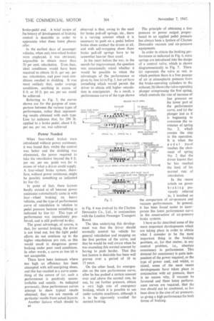
Referring to Fig. 5, the curves shown are for the purpose of comparison between the various types of performance, rather than representing results obtained with each type. Line (a) indicates that, for 200 lb. applied to a brake pedal, about 8 ft. per sec. per see. was achieved.
Power Needed
When four-wheel brake t were introduced without power assistance, it was found that, whilst the control was better and the skidding was eliminated, the power required to take the retardation beyond the 8 ft. per sec. per sec. point was far in excess of what a driver could supply. A four-wheel brake system, therefore, withbut power assistance, might be possibly something as indicated by line (b).
In point of fact, these layouts hardly existed at all because power assistance automatically came in with four-wheel braking on heavy vehicles, and the type of performance curve of retardation in relation to pedal pressure became something as indicated by line (c). This type of performance was immediately preferred, and is still preferred to-day.
The great advantage, of course, is that, for normal braking, the driver is not tired out, but the light pedal efforts do not continue up to the higher retardations pro rata, as this would result in dangerous power braking under poor road conditions. In other words, a curve as line (d) is not acceptable.
There have been instances where too high an efficiency has been attempted with self-energizing shoes, and this has resulted in a curve something of the nature of (e); such a performance is positively uncontrollable and unsafe. As indicated previously, these performance curves attempt to show typical results obtained; they are not records of particular results from actual layouts.
Another feature which should be B4 observed is that, owing to the need for brake pull-off springs, etc., there is a varying amount which it is necessary to push on a pedal before brake shoes contact the drums at all, and with self-wrapping shoes these brake pull-off springs have to be somewhat heavier than usual.
In the years before the war, in the search for improvement, the questioh was occasionally asked whether it would be possible to retain the advantages of the performance as given by line (c) in Fig. 5, but yet have something which would permit the driver to obtain still higher retardation in emergencies. As a result, a performance curve of the type shown in Fig. 6 was evolved by the Clayton Dewandre Co., Ltd., in conjunction with the London Passenger Transport Board.
The idea underlying this development was that the driver should normally control his vehicle for general retardation and stopping on the first portion of the curve, and that he would be well aware when he was exceeding this normal amount by having to push harder. That this last feature is desirable has been well proven over a period of 10 to 15 years.
On the other hand, for emergencies on the new performance curve, after he has pushed a certain amount over and above the normal rate, he can, by yet further pressure, obtain a very high rate of emergency braking, which it is possible to use under suitable conditions, although it is to be rigorously avoided for normal braking. The principle of obtaining a line pressure or power output proportional to an applied pedal pressure has always been a fpature of Clayton Dewandre vacuum and air-pressure equipments.
In order to obtain the braking performance as indicated in Fig. 6, extra springs are introduced into the design of a control valVe, which is shown diagrammatically in Fig. 7. There, (a) represents the valve at rest, in which position there is a free passage of air at atmospheric pressure from the brake-operating cylinders to the exhaust; (b) shows the valve-operating plunger compressing the first spring. which controls the rate of increase of line pressure on the lower part of the performance curve, and (c) the plunger just as it is beginning to overcome the resistance of spring No. 2, which creates the step in the operation. It is when the pedal travel reaches the abutment of spring No. 2 that the driver knows that he has reached the limit of his normal rate of retardation.
In the recent article on power braking previously referred to, I touched on the comparison of air-pressure and vacuum performances. In' general, it has been found easier to incorporate this latest performance curve in the construction of air-pressure brake systems.
I have so far described some of the more important developments which are taking place in order to obtain what I consider to be the most important thing in the braking problem, or, for that matter, in any control problem, i.e., absolute consistency in performance. This demand for consistency is quite independent of the power required, or the type of power used, and whilst, as stated, some of the most recent developments have taken place in conjunction with air pressure, there is no reason why, if vacuum be favoured and these latest performance curves are required, that the two should not be combined, as has been done in the case of air pressures. so giving a high performance for both forms of braking.
OPEN
.t1114
TO BRAKE OPERATING CYLINDERS NLET ALVE SEATED FROM Ale-PRESSURE RESERVO R ON TROLL ED
BY COMOPRFESSION
SPRING No I