


Inlet Restriction to Govern Injection Pump
Page 34
If you've noticed an error in this article please click here to report it so we can fix it.
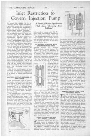
A Resume' of Patent Specifications That Have Recently Been Published
I N patent 'No. 551,869 by S. A. Adolphe Saurer, Arbon, Switzerland, a governing system for oil engines is shown. The device used is exceedingly simple and can be adapted to any existing pump, without alteration. The drawing shows, diagrammatically, an injection pump (6) of the conventional type and the additional governor unit. The latter comprises an • engine-driven positive pump (4), which delivers fuel to a cylinder containing a spring-loaded piston (2). This is centrally drilled at 3 to communicate with two cross-bores, one of which Seeds the pump inlet (1) whilst the other (5) leads back to the supply tank.
When the eligine is stationary, the piston is in its lowermost pesition, leaving passage 1 open to the fuel supply via the central bore (3). When the engine starts, the rise of pressure from the pump tends to lift the piston and so throttle passage 1, at the same time opening the return path (5). Sufficient overlap is provided to ensure a stable working condition, but if the engine speed should rise above the set value the fuel supply would be effectively throttled by the piston and so bring the governing action into operation.
This device would appear to have the merits of simplicity in construction, and ready and immediate adaptability to a variety of engines and injection pumps.
IGNITION CONTACT-BREAKER OF NEW FORM 'THE conventional type of contact, 1 breaker rocker arm has undergone little change for many years, but that it is still capable of improvement is demonstrated by a modified design shown in patent No. 551,938 by the British Thomson-Houston Co., Ltd., and others, Crown House, Aldwych, London, W.C.2.
The drawing shows, in perspective, the suggested form, which is rather smaller and lighter than usual. The rocker is provided with the usual pivot hole (4), a cam-engaging heel (3) and a contact point (2). The whole component is made from laminated resinbonded fabric, the plies of which are located end-on to the cam, hut which fold around the contact point (2). The spring blade is attached in the position shown and is secured by a rivet (1), The advantages claimed are lightness and durability, due to reduced bounce and low-impact pressure, all of which tend to give the device a high-maximum operating speed.
OIL-ENGINE INJECTOR WITH CORUNDUM NOSE-PIECE
FRON! Scintilla Ltd., Soledre, Switzerland, comes patent No. 551,912, in which is described an improved design of injection nozzle for oil engines. Two noteworthy features are embodied, the use of a corundum nozzle and a means for inducing turbulence in the fuel during injection.
In the drawing, a spring-loaded plunger (8) is held on to its seating (3) to close oil the lower end in which the corundum jet (4) is located. Fuel under injection pressure arrives via passages (1 and 2) and uncovers the seating by lifting the plunger. The
tw o• passages do not open dtrectly to the
under-space, but are deflected in a tangential
direction near the bottom. This creates a powerful whirl, the result of which is that the fuel leaves the injector in a wide-angled cone of spray.
Reasons given for the choice of corundum for the insert (4) are that it is hard, chemically and thermally stable and capable of taking a high degree of polish.
Recently, the production of large sapphire houles has been accomplished at economical cost in U.S.A. In this form, corundum (or crystalline aluminium oxide) . will be readily available for purposes such as that described here; drilling and polishing techniques have been improved, and cheap mass production of the jets is quite feasible even now.
ROBOT CONTROL FOR ANY SELF-PROPELLED UNIT
A N ambitious scheme for the automatic control of vehicles, so that, unattended, they may traverse a predetermined path, is disclosed in patent No. 549,674. The idea is intended for application to agricultural machinery, fighting vehicles, aircraft taxi-lug on
aerodromes, lorries, buses and cars driving on roads under bad conditions of visibility, and so forth. The patentees are C. L. Paulus and R. K, Stout, both of Dayton, Ohio, U.S.A.
Basic principle is this: buried underground or laid on the surface are cables carrying alternating electric current; each machine has detecting equipment incorporating two coils, coupled to amplifying units, which control a servomotor on the steering gear. The circuit is arranged so that unbalance between the two coils moves the steering gear in a correcting direction. The vehicle, in the ease of a tractor, would be started and launched on its path over and along the cable, which it would then, it is claimed, faithfully follow. In the case of vehicles under the primary control of drivers, the guiding device would operate coloured lights on the dashboard, instead of directing the steering,
Whilst the scheme may be thought . somewhat impracticable, it is unwise, in theseclays of scientific progress, to assert that there is any routine duty that could not be performed by
machinery. One application that is definitely attractive is to a mower, which, once started, would carry on by itself until all the grass was cut.
The specification runs to 11 pages of text and includes 24 drawings—not a bad shilling's worth.
MAKING PISTON RINGS FROM POWDERED METAL
Fr HE. art of powder metallurgy is railidly advancing and Patent No. 551,232, from the British Piston Ring Co., Ltd., and others; of Coventry, .‘ describes how this technique can be applied to the manufacture of piston rings. The chief feature of the scheme is the method of making rings having the necessary sprung-open gap.
The rings are first formed by presslag powder into an annular groove in a die, only a slight gap being left during this operation. The ring is next treated in such a manner that it can be removed from the die and stretched to the sprung-open position and a packing-piece inserted in the gap. In this State the fmal heat-treatment is given, the ring remaining in the open position but having a curvature corresponding to•the correct diameter.
It should be noted that the use of powdered iron for piston rings is also dealt with extensively in an earlier patent, -No. 497,871,