


A Compact Forced-feed Lubricator.
Page 9
If you've noticed an error in this article please click here to report it so we can fix it.
Details of a New Mechanically-driven Oil-Pump Made by a Famous Firm.
After some of the freak ideas and forms of construction upon which the staff of this journal is, from time to time, requested to spend valuable time in examining and testing, the advent of an appliance which is distinguished by clean design and the ingenious application of approved mechanical principles, comes almost as a ray of winter sunshine.
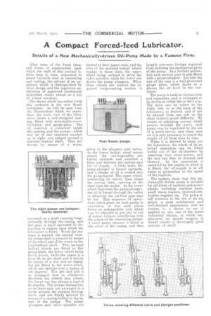
The device which has called forth this outburst is the new Bosch lubricator. As will be seen from the illustrations which we reproduce, the outer view of the lubricator shows a well-designed casting. fitted with detachable-cover, feed-pipe, and gauge-glass. The oil reservoir is contained inside this casting, and the pumps—which may be of any required number up to eight—are ranged around a common central shaft. They are driven by means of a worm, mounted on a shaft running longitudinally through the casing, and this gear is itself operated by the machine or engine upon which the lubricator is fitted. When the machine is started, the central vertical pump-shaft is rotated by means of the wheel and of the worm on the longitudinal shaft. Two inclined helical wheels are fitted to this pump-shaft, the lower wheel being firmly keyed, while the upper is a loose fit on the shaft and is driven by means of a slot and an engaging pin fitted to the lower-wheel, which can operate over a radius of 180 degrees. This pin and slot is so arranged that in whichever direction the wheels may rotate, the lower one has always a lead of 90 degrees. The pumps themselves, as we have said, are arranged in a circle around the central drivingshaft, and are firmly secured by means of a casting bolted to the inside of the casing. The pumpplungers and valve spindles are slotted at their upper ends, and the rims of the inclined helical wheels engage in these slots, the upper wheel being utilized to drive the valve spindles, while the lower one drives the pump plungers. When these wheels are rotated the required reciprocating motion is given to the plungers and valves. As the lower helical wheel moves round, the valve-spindles are forced upwards and establish a clear way between the suction and the oil supply. A little later, the pump-plunger is forced upwards, and a charge of oil is sucked into the pump-barrel. The upper wheel, continuing its travel, then closes the suction inlet, opening at the same time the outlet. As the lower wheel depresses the pump-plunger, the oil is forced through the outlet to wherever the oil-feed pipe may be led. This sequence of operations takes place on each pump in succession, so that each pump forms an independent unit, which may be adjusted or put into or out of action without interfering with the action of the remaining pumps. A small gauze strainer is fitted in the cover of the casing, and thus largely prevents foreign material from entering the mechanical parts of the pump. As a further precaution each suction pipe is also fitted with a gauze-strainer. Let into the side of the case is a well-protected gauge glass, which shows at a glance the oil level in the container.
The pump is made in various sizes and capacities, and is arranged to be driven at either 250 or 500 r.p.m. The drive can be either to the right, left, or at the back of the lubricator, as desired, and it can be altered from one side to the other without great difficulty. By means of adjusting screws, which project through the cover, each pump may be regulated by the use of a screw-driver, and when once set it is only necessary to renew the supply of oil from time to time. When it is desired to clean out the lubricator, the whole of its internal apparatus can be lifted bodily out of the oil-chamber by removing four cover-screws, and the case can then be drained and cleaned. As the apparatus is operated by the engine to which it is fitted, the oil-supply is at all times in proportion to the speed of the machine.
The makers claim that this mechanically-driven pump is suitable for all kinds of machine and power plants, including machine tools, small steam engines, internal-com bustion engines, etc. The pump itself presents to the eye of an en; gineer a most satisfactory and well-finished appearance, and we confess to a desire to see it applied to, say, one of the latest industrial chassis, in which employment we should imagine it would render a thoroughly good account of itself.