


Heat Control of Cylinders in Steam -driven
Page 56
If you've noticed an error in this article please click here to report it so we can fix it.
D ESEARCH is still proceeding in the
direction cf steam propulsion, and the latest proposals are embodied in patent No. 607,611, which comes from a pioneer concern, the Stanley Steam Motors Corporation, Chicago, Illinois, U.S.A.
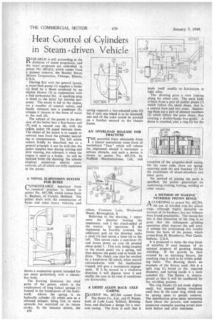
Dealing first with the general layout, a water-feed pump (I) supplies a boiler (2) fired by a flame produced by an electric blower (3) in conjunction with a fuel carburetter-(4). A sparking plug is fitted to the latter for starting purposes. The steam is led to the engine, via a number of control valves, and finally exhausts into a condenser (5), whence it returns in the form of water to the well (6).
The subject of the patent is the division of the boiler into a first-heater coil (7) and a second one (8), with the engine jacket (9) piped between them. The object of the jacket is to supply or subtract heat from the cylinder according to circumstances. The full action cannot briefly be described, but as a general principle it can be said that the jacket supplies heat during starting and slow running, but subtracts it when the engine is used as a brake. As will be realized from the drawing, the scheme employs numerous electric autocontrols, all of which are fully explained in the patent.
• A NOVEL SUSPENSION SYSTEM FOR BUSES
CONSIDERABLE departure from standard practice is shown in patent No. 607,708, which comes from L. Baghuis, of Utrecht, Holland. The patent deals with the construction of buses and other heavy vehicles, and
shows a suspension system intended for use more particularly with a chassisless body.
The drawing illustrates the chief point of the patent, which is the employment of long helical springs (I) housed in the frame-posts of the body work. Above the spring, is an hydraulic cylinder (2) which acts as a rebound damper, being free to move upwards but restricted on its return stroke. In the instance shown, the a30 spring supports a two-wheeled yoke (3) but if only one wheel is to be mounted, one end of the yoke would be pivoted on a bracket secured to the chassis frame.
AN OVERLOAD RELEASE FOR TRACTORS
T"powerful force obtainable from a tractor necessitates some form of mechainical " fuse " which will release the implement should it encounter a serious obstacle, and such a device is shown in patent No. 607,514, by Nuffield Mechanizations, Ltd., and
others, Common Lane, Heath, Birmingham, 8. Washwood Referring to the drawing, 1 represents the drawbar hauling the implement, and 2 the clutch-pedal of the tractor. In operation, if the implement be forcibly arrested, the additional pull on the drawbar rocks a shift (3) and moves a lever (4) to the left. This action rocks a cam-lever (5) and forces down an arm (6) pivoted about point 7. This arm, being coupled to the clutch pedal via a spring, will then depress the pedal and so break the drive. The clutch can also be worked by a hand-lever (8) which, when moved anti-clockwise with the mechanism tripped, will give a momentary engagement. If it be moved in a clockwise direction it will depress lever 6 and enable the cam to be reset if conditions are favourable.
A LIGHT ALLOY BACK AXLE CASING
PATENT No. 607,504 comes from 1 The Rover Co., Ltd., and 0. Poppe, both of Lode Lane, Solihull, Birmingham, and discloses a design for a rearaxle casing. The form is such that it
lends itself readily to fabrication in light alloy.
The drawing gives a view looking along the wheel axis. The main body is built from a pair of similar plates (1) which follow the usual shape, that is, a central boss and two arms. Separating these are a pair of channel members (2) which follow the same shape, thus creating a double-banjo box-girder. A dome is attached; also a ring (3) for the reception of the propeller-shaft casing.
On the outer ends, there are springreceiving pads (4) and brackets (5) for the attachment of shock-absorbers and other parts.
No method of joining the parts is specified; the patent generalizes by mentioning riveting, bolting, welding or other means.
A METHOD OF MAKING NITRIDED PISTON RINGS
A CCORDING to patent Na. 607,701, /-1 the use of nitrided iron for Piston rings, although highly desirable on account of its hardness, has not hitherto been found practicable. The reason for this is that distortion of the ring is so great that the subsequent grinding operation often exposes the soft core. A scheme for overcoming this trouble forms the basis of the patent, which comes from H. Bramberry, New Castle. Indiana, U.S.A.
It is proposed to make the ring blank of nitralloy N steel because of its unusual property of. growing during nitriding. if the growth be then resisted by an enclosing fixture, the resulting ring is said to be within grinding limits. The drawing shows an example of the fixture used; this is a split ring (1) bored to the required diameter, and having inside it a male mandrel (2). The fixture is electroplated so that it will be unaffected by the nitriding process.
The ring blanks (3) are made slightly small, but expand during treatment until they fit the outer ring, which can be sprung open to permit removal. The specification gives many interesting facts about the process, and contains numerous examples quoting actual sizes both before and after treatment.